Industry: Hydrocarbon Development

  • Cryogenic Plant Optimization

    Cryogenic Plant Optimization

    The Challenge

    CANUSA EPC’s Client needed to determine the capability of throughput capacity for a dual-train plant related to rejection and recovery operations. Due to the minimum operating costs of the plant, the Client wanted to evaluate which major equipment could be upgraded to allow single or dual-train operations. Along with restriction conditions, the client desired to understand nameplate operating limits and applicable constraints.

    The Solution

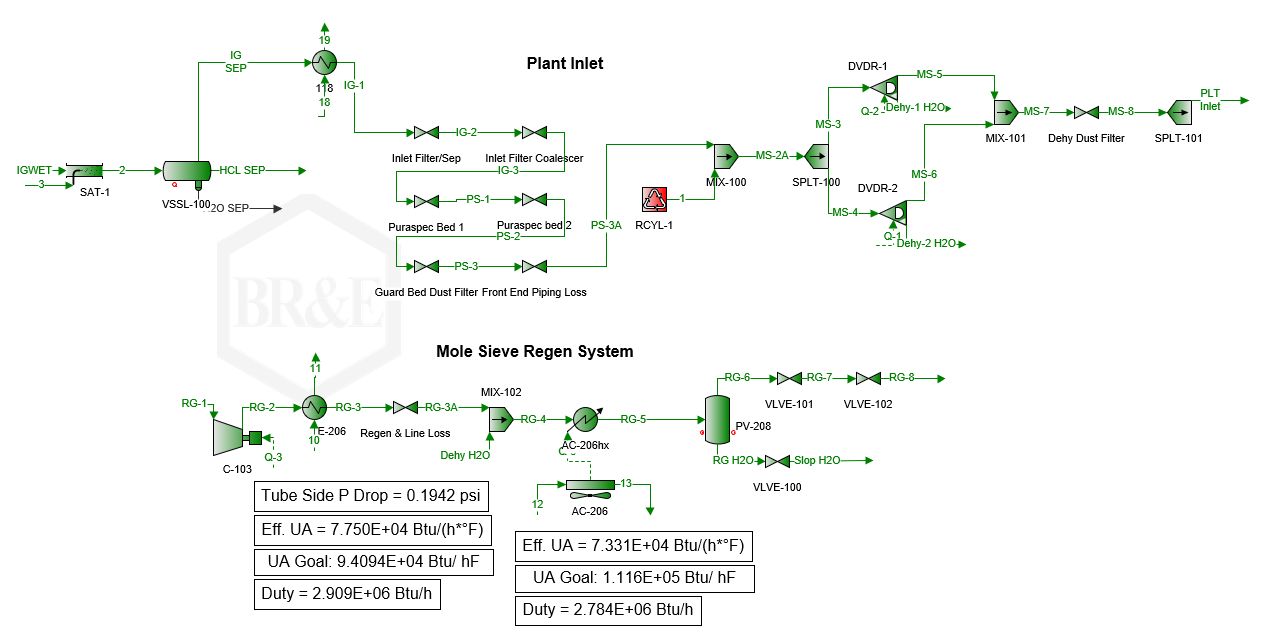
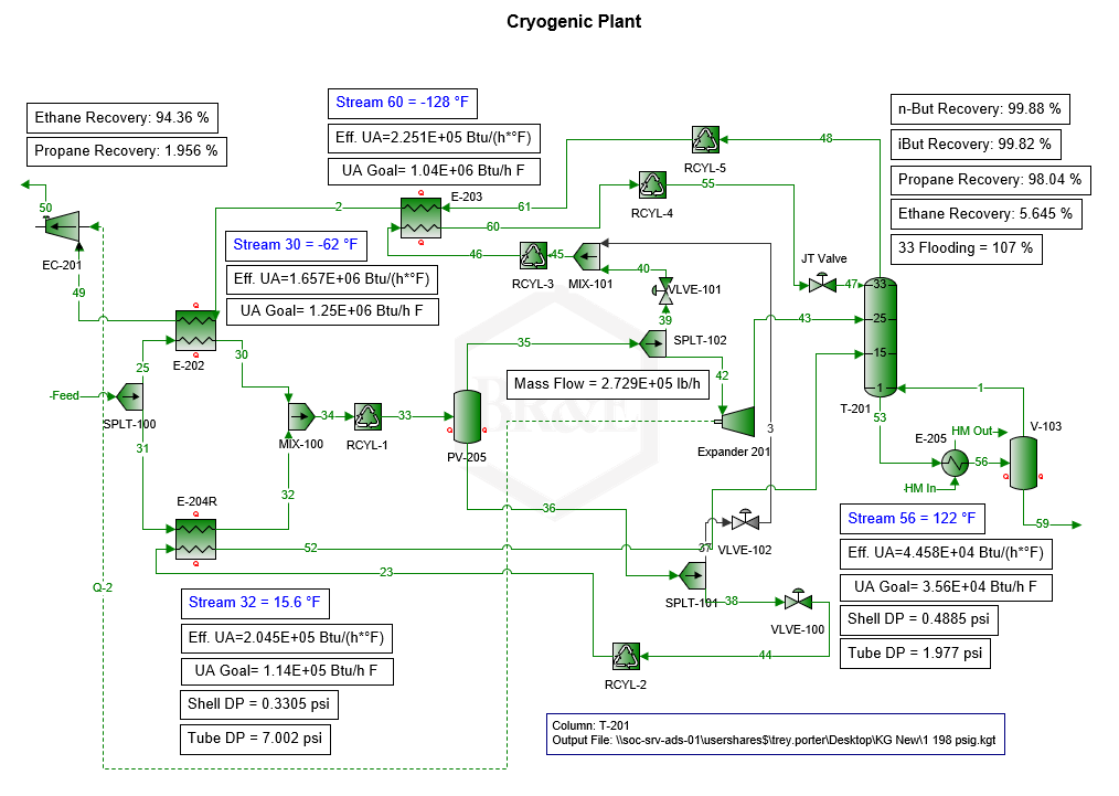
    CANUSA EPC conducted a debottlenecking study to evaluate throughput limiting conditions related to various operating limits for pieces of equipment like guard beds, mole sieves, heat exchangers, towers, etc. Along with equipment considerations, CANUSA EPC ran scenarios for the rejection and recovery operations.

    Process models of the major equipment in ProMax:

    • Modeled cryogenic process for rejection and recovery modes
    • Engaged vendors to determine plant inlet pressure drops through filters/guard beds
    • Simulated mole sieve regeneration/dehydration loops
    • Evaluated residue gas compression and heat content
    • Determined heat transfer properties for exchangers/aerial coolers

    Debottleneck Evaluation:

    • Evaluated key equipment results to remain within equipment limits
      • Tower flooding within KG Tower software
      • Convective heat transfer for heat exchangers and aerial coolers
      • Dehydration media, cycle times, and saturation for mole sieve units
      • NPSHa vs. NPSHr for product and heat-medium pumps
      • Mass flow for expander-compressors
      • Compressor HP and available head capabilities
    • Evaluated nozzle momentum with K-factors and pressure drops across all equipment
    • Evaluated liquid retention time and vapor entrainment for vessels
    • Evaluated the effect on recoveries as plant inlet flow increases

    The Results

    • Determined minimum requirements to increase the throughput of each train by 20 MMSCFD
    • Summarized for operations major equipment restrictions for both recovery and rejection modes
    • Worked with filter vendors to determine maximum operating limits based on filter components
  • Cryogenic Electrical System

    Cryogenic Electrical System

    The Challenge

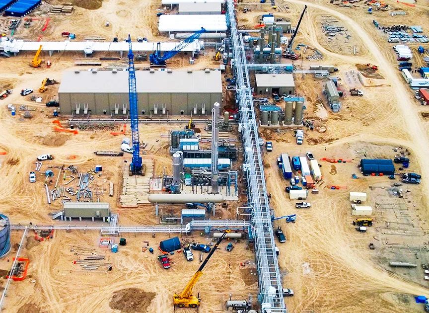
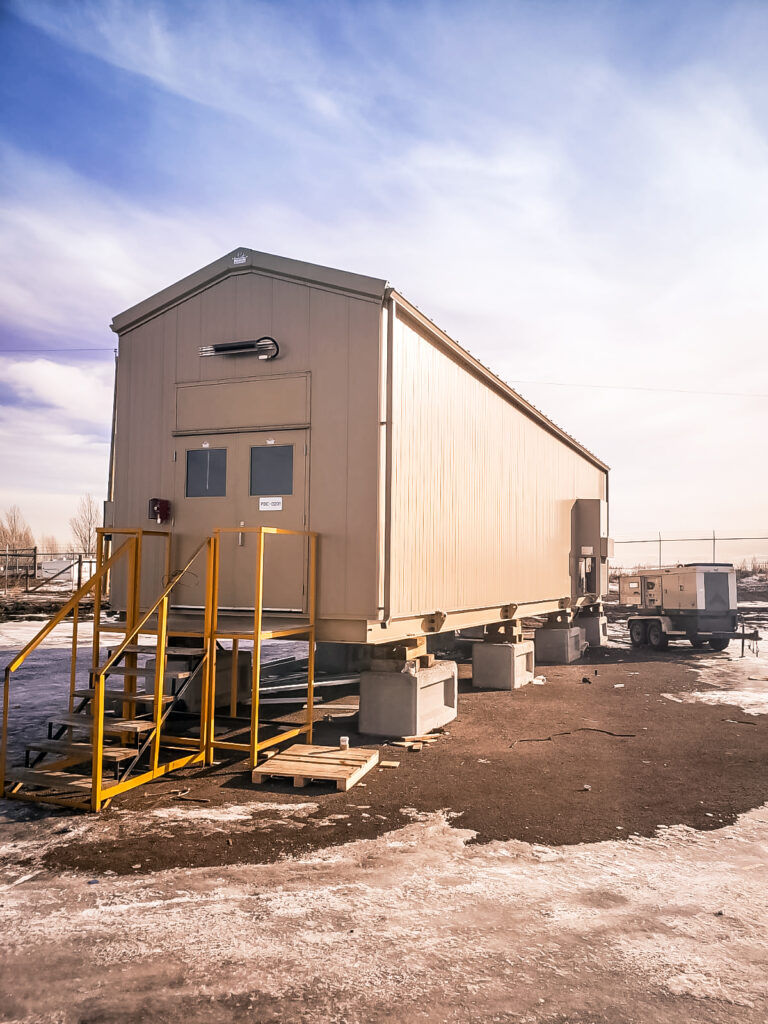
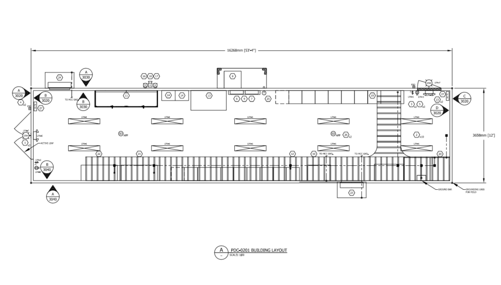
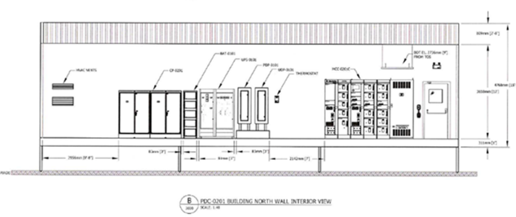
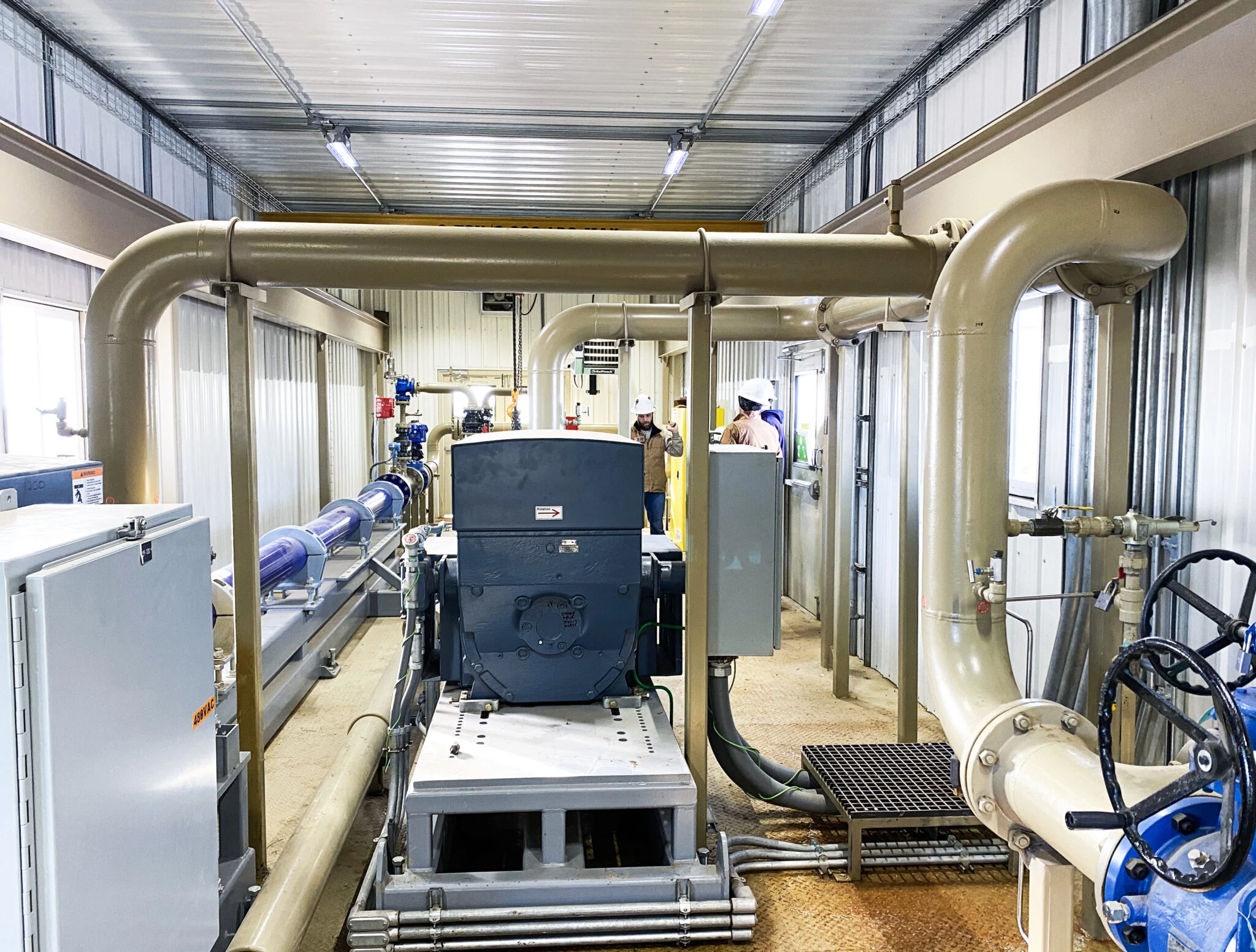
    Our Midstream Client required an electrical system consisting of medium and low voltage PDC buildings as part of their 200 MMSCF/day cryogenic facility which was executed as an EPC model with a large packager. There was a desire to provide an integrated motor control system with the site control platform, but also distribute the system to lower the total installed cost of the package.

    The Solution

    Designing for Construction:

    • Designing for Construction
      • The electrical system was designed to minimize cable runs by placing the buildings closer to the equipment
      • Distributing the electrical system into multiple buildings provided ease of transport and unloading and allowed for staged construction
      • Integration of the PDC and control system minimized onsite interconnects

    Executing to Deliver on Cost & Schedule:

    • Structured a Lump sum supply of (4) PDC buildings including MV and LV systems and control systems to control costs
    • Selected sparing capacity on MCC lineups to accommodate changes from the process/mechanical team
    • Executed integrated testing before shipment to ensure minimal onsite changes

    The Results

    • Low voltage buildings arrived before select mechanical packages allowing for electrical to execute in parallel to mechanical
    • Allowed for addition of VFDs from late changes to the design
    • Bottom entry connections lowered installation costs
  • Heavy Oil Battery

    Heavy Oil Battery

    The Challenge

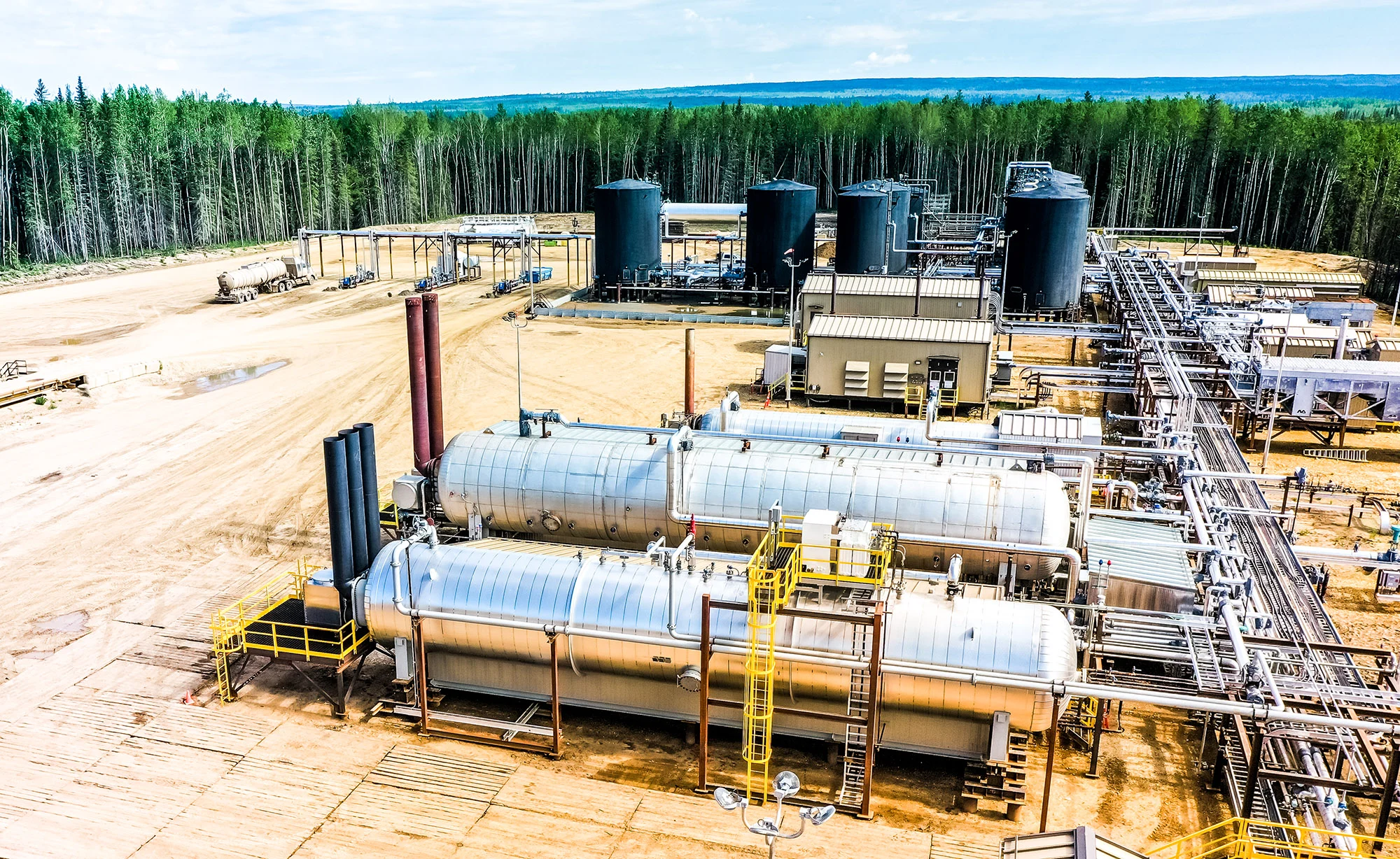
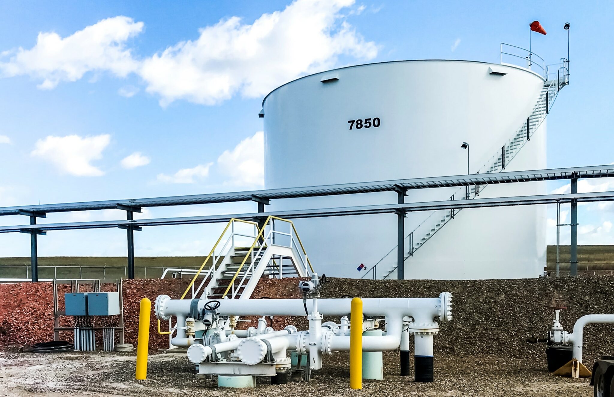
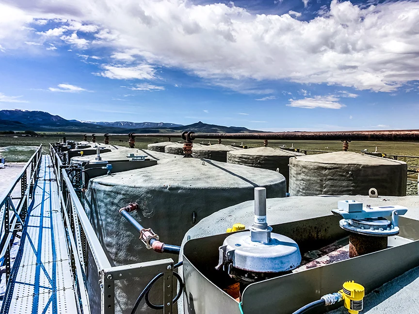
    Additional oil production from the Clearwater formation required our client to increase the processing capacity of an existing heavy oil battery from 8,000 BPD to 15,000 BPD. Due to the future plans to convert the field to waterflood, the upgraded battery equipment needed to be adequate to handle future water volumes. Functionality for crude oil blending with condensate and NGL was required to meet RVP, density, and viscosity specifications in the sales oil pipeline.

    The Solution

    CANUSA EPC was contracted to offer Engineering, Procurement and Construction Management (EPCM) services.

    Developing a Plan to Meet Client Expectations:

    • Leveraged CANUSA EPC’s previous battery design experience
    • Developed a DBM to manage design expectations
    • Developed a PEP and schedule to efficiently manage execution

    Sourced New Equipment:

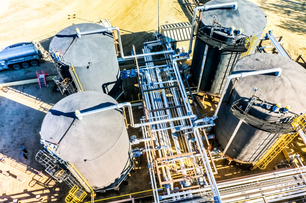
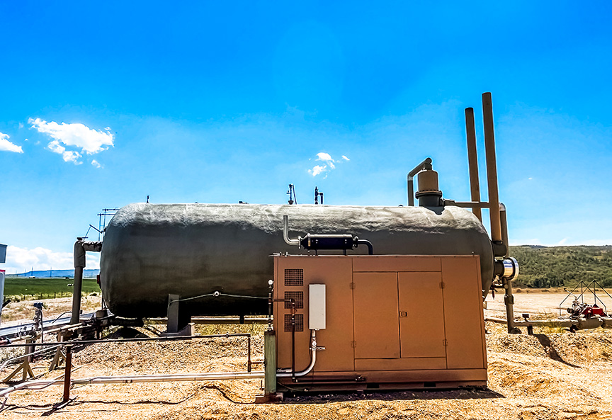
    • Oil and Water Tanks
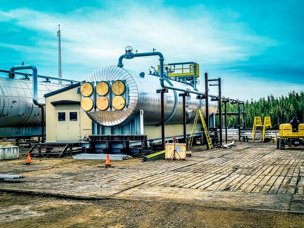
    • Electrostatic Heater Treater
    • Glycol Boiler and Cooler
    • Waste Heat Recovery Building
    • LACT Sales Oil Booster Pump
    • Sales Oil Blending Package

    Execute Value Engineering to Support the Project Schedule:

    • Identified operational improvements for the upgraded battery
    • Automated tank selection and facility de-sand
    • Rectified deficiencies discovered in the existing battery during construction

    The Results

    • Increased oil production from 8,000 BPD to 15,000+ BPD
    • Lowered emissions of produced oil
      • Implementation of a VRU to the tank farm
      • Utilizing electrostatic treater to reduce energy and chemical requirements of treating oil
      • Waste heat recovery reducing overall plant fuel gas consumption
    • Operations improvements
  • Oil Terminal Expansion

    Oil Terminal Expansion

    The Challenge

    The Client needed to design and install an additional oil sale point in the DAPL pipeline for a capacity of 1000 BPH. The existing facility had an existing 480V utility drop that would need to be utilized for 600 HP motors.
    The Client was executing the project through an approval process requiring engineering definition to a Class 3 estimate before completing the design for construction.

    The Solution

    CANUSA EPC provided engineering and procurement services to the Client to expedite the project schedule.

    Engineering:

    • Site visit to inventory repurposed equipment
      • FEED Study including TIC estimate
      • Full discipline engineering and design
      ▪ Installation of a repurposed pump skid
      ▪ Electrical meter connection
      ▪ Meter run specification
      ▪ 20” Pipeline section to DAPL connection, including
      launcher/receiver
      ▪ ARC Flash updates
    • Construction designs for skid equipment installation strategy

    Procurement & Project Services:

    • Schedule, budget, and scope management with our project services
    • Specification of valves, meters, pig launcher
    • Bid solicitation of electrical switchgear, motor-operated valves
    • Bid analysis from vendor submissions
    • Expediting

    The Results

    • Client site increased sales capacity to new pipeline connection at a rate of 1000 BPH.
    • $2.5 Million USD budget managed
    • Utilized existing pump skids to reduce the total cost of the project.
    • Provided support through construction for client facility startup.
  • Central Tank Battery Expansion

    Central Tank Battery Expansion

    The Challenge

    The Client was operating an existing Central Tank Battery with an existing separator and heater treater onsite for servicing the production facilities. This CTB was also the sales point for the gas from the production facilities. The Client wanted to increase the storage capacity onsite by 5000 BBL and add Vapor Recovery Units to meet tank emissions requirements. There was also a need to increase the inlet capacity to treat production for two new pads, targeting on line production shortly after the expansion of storage.

    The Solution

    CANUSA EPC first engaged with site visits to understand the existing infrastructure onsite and determine how the operations team had previously built the existing assets.

    Our team provided as-built documentation of the existing facilities after the completion of a site visit. The construction design scope included:

    Engineering:

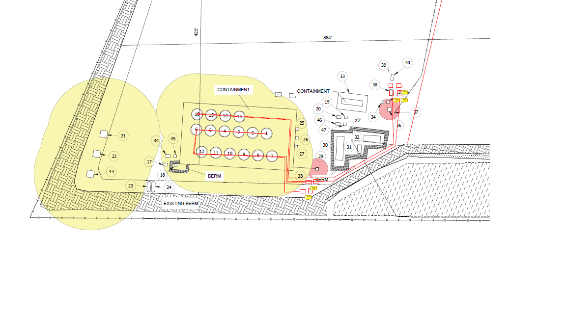
    • Facility plot plans and containment sizing for new tanks
    • P&IDs of the facility
    • Generation of pipe valve and fitting material based on the P&IDs
    • Mechanical tie-in of a new VRU to meet Colorado AQCC Reg 7
    • Area classification updates
    • Single line updates
    • Design of an electrical system for the expansion
      • Electrical
      • Controls
      • Instrumentation

    The Results

    Design and expanded two Central Tank Batteries

    Designed expansion of an existing production facility and a new greenfield pad

    Reusable equipment

    • Provided onsite support of equipment walkdown for existing package redeployment

    Designing for expansion capacity

    • 900 barrels of added field production
    • Existing electrical systems were evaluated to handle future needs for pumps and VRU packages
  • Pipeline System Expansion

    Pipeline System Expansion

    The Challenge

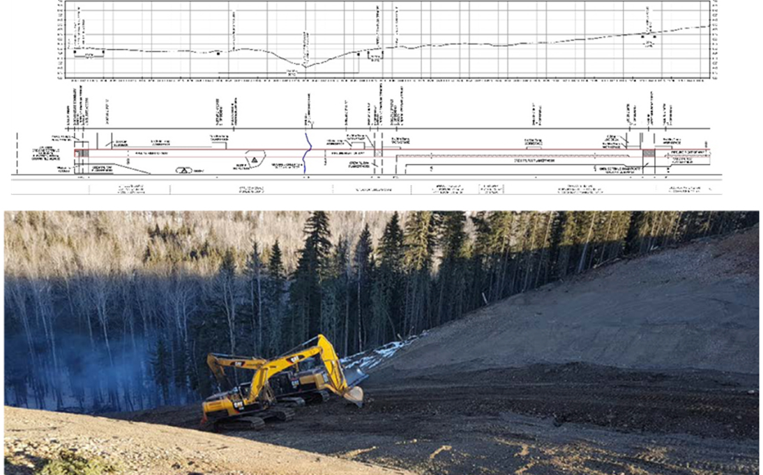
    British Columbia has stringent pipeline regulations and the geography presents harsh weather and steep/diverse terrain. Due to the project’s construction size, nearly 60 vendors were required over the 10+ month schedule. With various constructability issues, especially pertaining to hydrotesting, de-watering and purging operations, the Client required a team with experience and the right tools to complete the project.

    The Solution

    • CANUSA EPC provided a single point of contact for all 59 vendors
    • Designed and coordinated to safely cross large rivers while meeting all environmental regulations
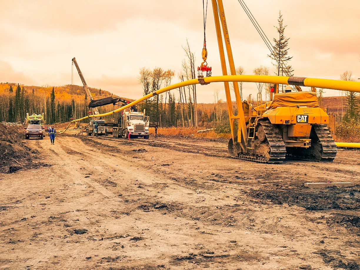
      • Septimus NPS 8 sales gas and gathering pipeline loop (combined 9,800+ meters; river crossings)
      • Monias NPS 12 sales gas, NPS 6 natural gas and NPS 6 liquid pipeline constructions (combined 55,600+ meters)
      • Saturn NPS 16 sales gas pipeline construction (combined 23,900+ meters; river crossings)
    • Design of the pipeline pigging facilities for 900 ANSI system under CSA specifications
    • Daily, weekly and monthly project reporting including budget, schedule, safety and quality
    • Sweet natural gas and condensate pipelines were constructed as spare bi-directional lines for future production

    The Results

    • Improved capacity and flexibility of the gathering and sales pipeline system
    • NPS 16 sales gas pipeline connected the NPS 12 pipeline from existing gas plant
    • Transported sweet natural gas from the field to the existing gas plant – allowing for incremental gas production
    • Provided flexibility for Client logistics with bi-directional designs
  • 120 MMSCFD Compressor Site Expansion

    120 MMSCFD Compressor Site Expansion

    The Challenge

    Growing gas production necessitated our client expand one of their compressor stations, doubling the capacity and total installed horsepower. The original design of the low-pressure inlet was originally designed for two slug catchers, leading to concern over liquid management onsite. The high-pressure inlet did not allow for blending for dehydration optimization. Late into execution of the project, the existing high-pressure 3-phase separator was upsized to improve liquid removal and dehydration performance.

    The Solution

    Developed a plan and budget:

    • Executed onsite visits and as-built documentation of existing facility
    • Reviewed operational improvements for the expansion
    • Developed design basis to capture required project technical requirements

    Source new equipment:

    • Low-pressure inlet slug catcher
    • High-pressure 3-phase separator
    • Motor Control Center (MCC) expansion

    Execute value engineering to support the project schedule:

    • P&ID generation
    • Equipment evaluation
    • PSV sizing calculations and safety review
    • Engineered valve specification
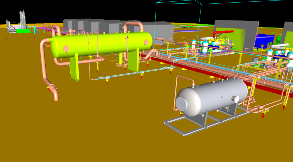
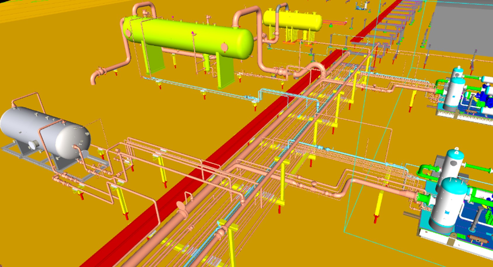
    • 3D modeling
    • Construction packages for electrical, mechanical, and civil bids

    The Results

    Engineering:

    • Up-to-date engineering package for the site
    • Future compressor additions require no additional mechanical design
    • Developed plan for short shutdown window for tie-ins

    Operations:

    • Addressed issues with high-pressure drains to VRU
    • Improved isolation and access to compressor packages
    • Consolidated planned equipment for a two-inlet design to single inlet
  • Greenfield Compressor Station

    Greenfield Compressor Station

    The Challenge

    Additional gas production in the basin required our client to build a new compressor station, doubling the client’s compression capacity in the area from 120 MMscfd to 240 MMscfd. Due to the increasing CO2 content of the gas in the basin, the new station needed to include future Amine gas treatment in addition to gas dehydration. Functionality for gas blending from other high-pressure inlet sources with the sales gas was required to meet CO2 content and sales gas specifications in the short term. The client also wanted functionality to be able to combine low-pressure and high-pressure liquid products through a single sales pipeline.

    The Solution

    CANUSA EPC provided full discipline engineering to develop the construction packages for the client.

    Developing a Plan to Meet Client Expectations:

    • Leveraged the client’s previous compressor station design from CANUSA EPC
    • Identified operational improvements for the new station

    Sourced New Equipment:

    • Low Pressure Inlet Slug Catcher
    • Heater Treater
    • High Pressure 3 Phase Separator
    • Pipeline Pumps
    • Motor Control Center Building

    Execute Value Engineering to Support the Project Schedule:

    • Redesigned layout for Glycol Heater Package
    • Sized VRU package for expansion
    • Specified switchgear and MCC equipment to remove from the critical path
    • Reduced the height of the slug catcher package to lower site construction costs

    The Results

    Provided Construction Package with Designs for Future Expansion

    • Future site compressor additions require no additional mechanical design
    • Design allows for additional inlets and Amine unit

    Operations Improvements

    • Consolidated low-pressure inlets to allow for a single slug catcher vessel
    • Addressed issues with high-pressure drains
    • Improved isolation, access, and piping for compressor packages
  • Greenfield 50 MMSCFD Compressor Station

    Greenfield 50 MMSCFD Compressor Station

    The Challenge

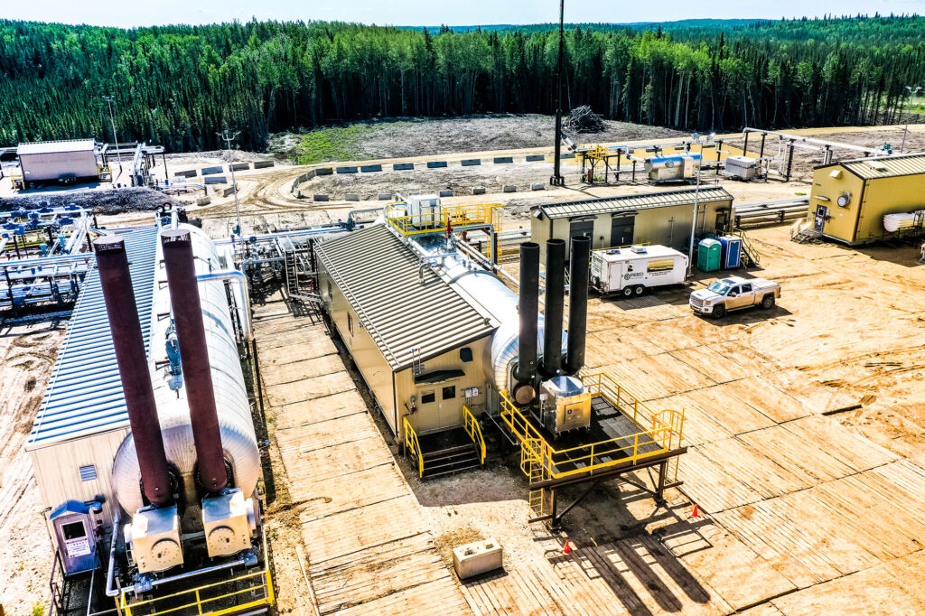
    The client had an aggressive drill program that required compression, dehydration and sweetening of gas prior to entering into the Spectra Pipeline system. This project was extremely schedule driven – from conception to gas flowing in 7 months.

    The Solution

    CANUSA EPC provided engineering and procurement services.

    • Facility design was adapted to changing well pad and inlet conditions
    • Deployed dehydration, H2S sweeting for fuel gas and adjacent water handling system
    • Facility designs to handle an inlet pressure of 150 psig and an outlet pressure of 1200 psig
    • Artic packages utilized for speed of field deployment compared to field erected buildings

    The Results

    • The project was completed in 7 months by utilizing an existing design and a strong packager team
    • Deployed as an integrated field system to support a larger gathering system consisting of pipelines, well pads and a LACT
  • Composite Pipeline

    Composite Pipeline

    The Challenge

    Current development plans in the area required our Client to replace truck-in propane with pipeline quality fuel gas at their wellsite’s and battery facilities. To accommodate further development plans in the area, the pipeline required provisions to tie-in to future wellsite’s, batteries and pipeline segments.

    The Solution

    CANUSA EPC provided full discipline engineering to develop the construction packages for the Client.

    • Developed a plan to meet Client expectations
      • Leveraged previous pipeline design experience
      • Leveraged in-house process and design experts
    • Sourced materials
      • Pressure control valve
      • ESD valve
      • Carbon steel to HDPE transition pieces
      • HDPE line pipe and fittings
    • Executed value engineering to support the project schedule
      • Designed and implemented over pressure protection and pressure control to connect pipelines with different MOP’s
      • Worked with AER to expedite the pipeline license down from 6 weeks to 1 week

    The Results

    • Provided construction with a detailed work package
      • Installed 14 km of new fuel gas pipeline tying into 9 wellsites and 1 existing pipeline
      • Installed risers and blinds for future wellsite tie-in’s
    • Construction executed with minimal environmental impact
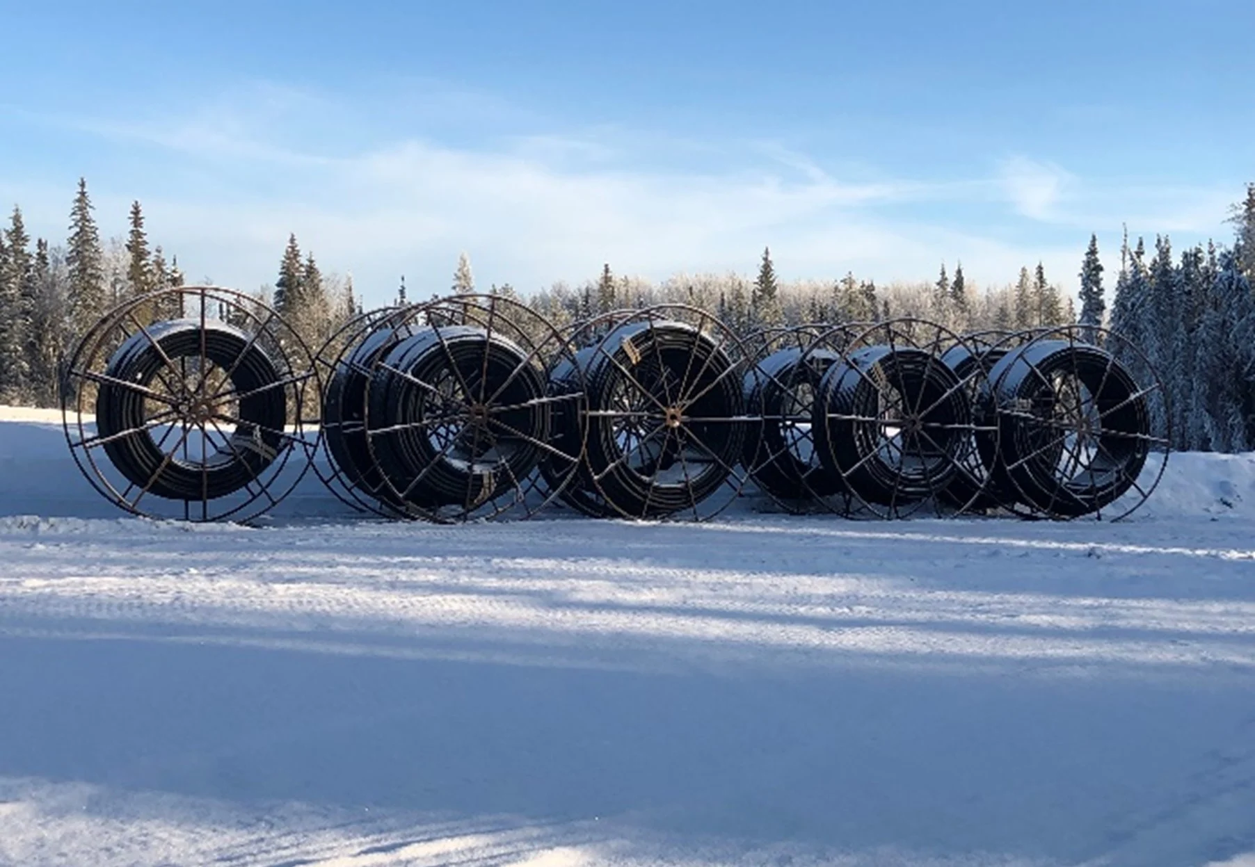
      • Pipeline was installed by plowing, minimizing disturbance to the surrounding area
      • Water course crossings HDD bored to minimize ecological impact