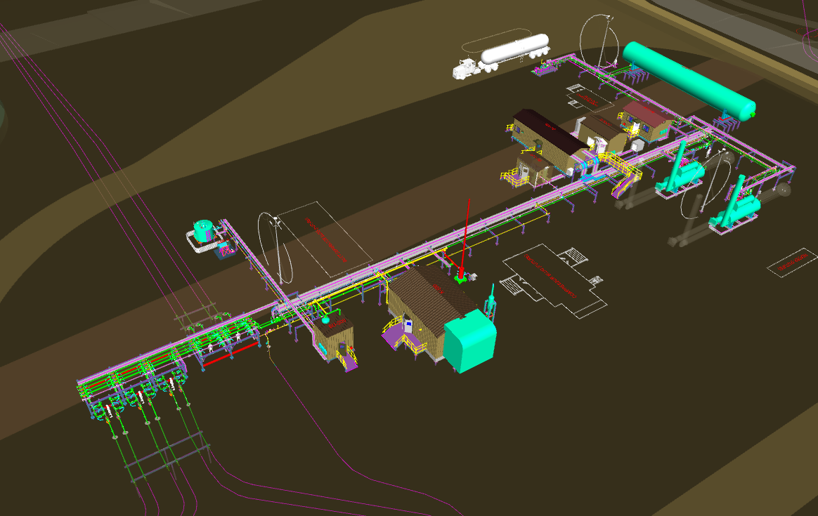
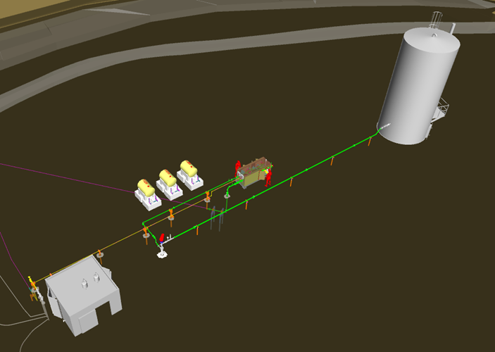
Carbon Dioxide is a proven solvent that is used to provide incremental oil production in Cold Heavy Oil Wells with Sand (CHOPS). Upstream clients use this type of Enhanced Oil Recovery (EOR) for incremental production from Brownfield areas and often need to increase CO2 supply for the EOR production program as it matures.
The Solution
Engineering:
Providing engineering support for upgrades to the following assets
At one of our recent ethanol projects, we were tasked with developing a relief solution for a dense-phase CO2 system. Like most early-stage sequestration sites in the U.S., this one had no simple way to recycle or offload off-spec product during a process upset. When working with dense-phase CO2, roughly 300 psi and as cold as -15°F, you’re dealing with a unique beast. It’s cold, high-pressure, and doesn’t behave like most fluids in a natural gas processing plant.
If the transport offtake shuts in or the CO2 goes off spec, the challenge becomes: how do you relieve this safely? What makes it especially challenging is how rapidly it changes states under relief conditions. This phase change can cause various operational issues and presents a massive safety hazard. API STD 521 is considered the bible, but this was one of those times when we had to look beyond the basic code.
Problems with Relieving Dense-Phase CO2
Safe operational design of CO2 capture facilities requires relief designs for dense-phase CO2 through a PSV. Relieving the CO2 liquid will induce a pressure drop and phase change, dramatically reducing the temperature during the relief. As the liquid expands, it pulls heat from its surroundings and transforms into a solid, sublimation effect. Dry ice begins to form at around -130°F. Relief temperatures can dip even lower, closer to -180°F. At these temperatures, you’re almost guaranteed to get solids that can:
Clog or choke the relief device,
Reduce flow capacity, or
Completely block the path to relief.
A blocked relief device means the vessel is no longer protected. Leaving you with a serious safety issue. As more CO2 capture and processing facilities are constructed, the normal approaches for relieving unsafe conditions won’t work for CO2. This requires that we develop solutions that protect the equipment while leveraging best practices from the industry.
Code API STD 521 and Solid CO2 Plugging Risks
API STD 521: Guide for Pressure-relieving and Depressuring Systems is the go-to standard for pressure-relieving systems, as it acknowledges this flash freezing issue. Section 4.9.2 touches on “Liquid-Vapor Mixture and Solids Formation” and warns about the potential for flashing fluids to cause choking or blockages. It also cites wet propane as an example of a fluid that can form solids.
However, there’s an issue. API STD 521 states that “some fluids (e.g. carbon dioxide and wet propane) can form solids when they are discharged through the relieving device. No uniformly accepted method has been established for reducing the possibility of plugging”.
There’s no established method to reliably predict or mitigate plugging caused by solid CO2 formation. It tells you the hazard exists but leaves the solution up to you. This was the biggest gap we have found and had to address in the design of our CO2 capture facilities.
An Approach to Pressure Relief for CO2 Processing: “Burping” CO2 Safely
We started with a question: What’s the safest way to handle relief of pressure for dense-phase CO2 that can’t be recycled or sent down the line?
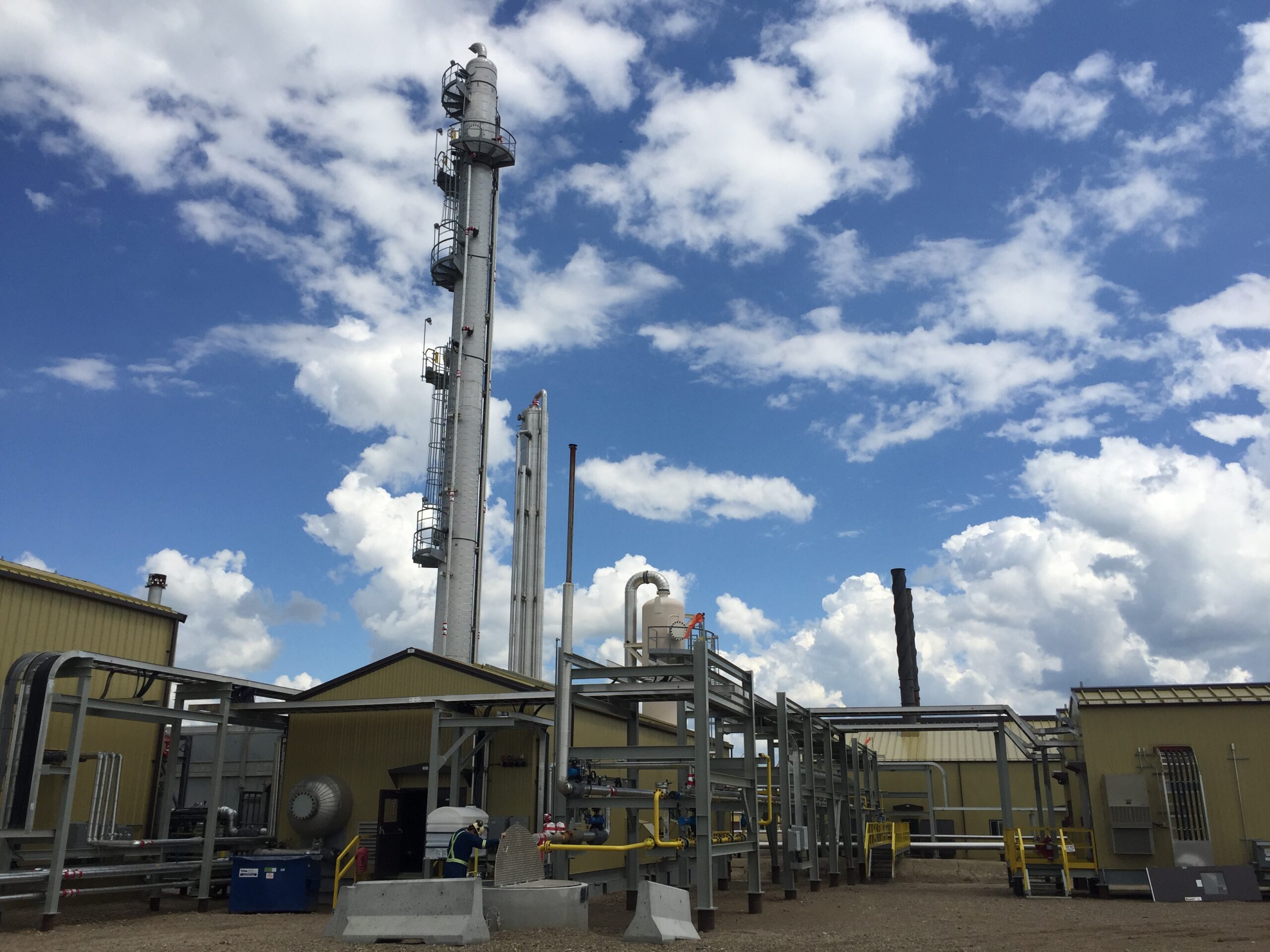
One solution we have designed in our processing facilities for CO2 is to block and hold the system and send large volumes of the dense phase liquid to the distillation column through control valves that trigger based on plant upsets. The column is capable of holding large volumes of CO2 and any amount that vaporizes while being held can naturally vent through the overhead vent.
Thermal relief valves (TRV’s) are used to protect any equipment and piping that can possibly be isolated by check valves and can’t be sent to the distillation column during a block and hold scenario. While a pipeline is shut in, and if the pipeline is exposed to a heat source, such as heat from solar radiation or even ambient conditions during hot summer months, the internal process material will also heat up, expand, and increase pressure. In this case, the CO2 is at the bubble point and can vaporize with heat exposure. If thermal expansion occurs, these TRV’s will relieve this isolated high-pressure vapor, and prevent over pressurization of the system. Once the vapor is relieved, the TRV will reseat, and not allow further relieving.
This constant relieving and reseating, or “burping” of warm, vaporized CO2 will reduce the risk of relieving dense phase CO2. This approach avoided the extreme phase change that commonly resulted in dry ice plugs.
The Trading Off to Venting CO2: Safety vs. Speed
Burping CO2 is a potentially time-consuming process. The maximum amount of dense phase CO2 possible is sent to the distillation column. However, this CO2 still has to vaporize naturally. The CO2 is condensed at bubble point temperature, so the delta temperature it has to overcome is relatively small, allowing the CO2 to vaporize in a relatively reasonable amount of time. The phase change, however, still imposes temperature issues due to the Joules-Thomson effect, and still has risk of plugging up the vent piping. Careful pressure monitoring of this vent is implemented to mitigate this risk.
The remaining CO2 to be relieved by the thermal relief valves will naturally reset once vaporized CO2 is relieved, naturally mitigating the risk of freezing and plugging. Considering the size of a plant, this can quickly take a long time to relieve an entire process. At CANUSA, we believe that this careful vapor relief vs. the prevention of piping freezing and plugging method is the safest known relief strategy for dense-phase CO2 if no recycle solution is available.
CO2, unlike the relief of natural gas, is heavier than air and will sink or collect in low-lying areas. Therefore, venting locations need to be considered for safe release to ensure that de-oxygenated zones don’t form and there is adequate dispersion. Typical solutions include a vent pipe from the CO2 relief valves to higher elevations to allow the CO2 to disperse. A slower release using the Burping method will release smaller amounts of CO2 over a longer period, reducing the risk the accumulation to unsafe concentrations. OSHA incidents for CO2 handling indicate how important dissipation considerations are for the safe operations of these facilities.
Considering Process Solutions to Reduce CO2 Venting
Reducing the scenarios of release to the atmosphere not only increases the safety of the operations, but less vented CO2 will also contribute to higher capture rates and more revenue.
To reduce the scenarios of vented CO2, recycle designs can be incorporated into the process. For some facilities, a recycling approach using a closed-loop system via a cooler and blower can reduce the need to vent altogether.
This isn’t always economical. Controlled heating of dense-phase CO2 to transition to a gas phase takes considerable energy. The CAPEX of this type of system is often cost prohibitive for the low increase in recapture rate, but it could mean a true 100% capture operation.
Engineering Safety into CO2 Capture Facilities
This project made one thing very clear: the CO2 sequestration industry is evolving quickly, but the standards aren’t updating at the same speed.
We’re seeing more clients face similar problems – like what to do when a process upset sends off-spec CO2 surging through the system? API STD 521 offers the “what,” but not the “how”. Safety is vital; so, sharing solutions for the “how” is important.
Thoughtful engineering to manage dense phase CO2 during upsets
Minimal contamination of dense phase CO2 product – less than 10 ppm O2 in product
Limited venting to the atmosphere
Our team developed a practical, field-ready solution. It’s not fast. But it satisfied all of our clients’ requirements and was the safest design.
________________________________
HAVE INSIGHT ON THIS?
If you have experienced this or want to weigh in with your insights, please join the conversation on LinkedIn. Visit this post and see what others have to say!
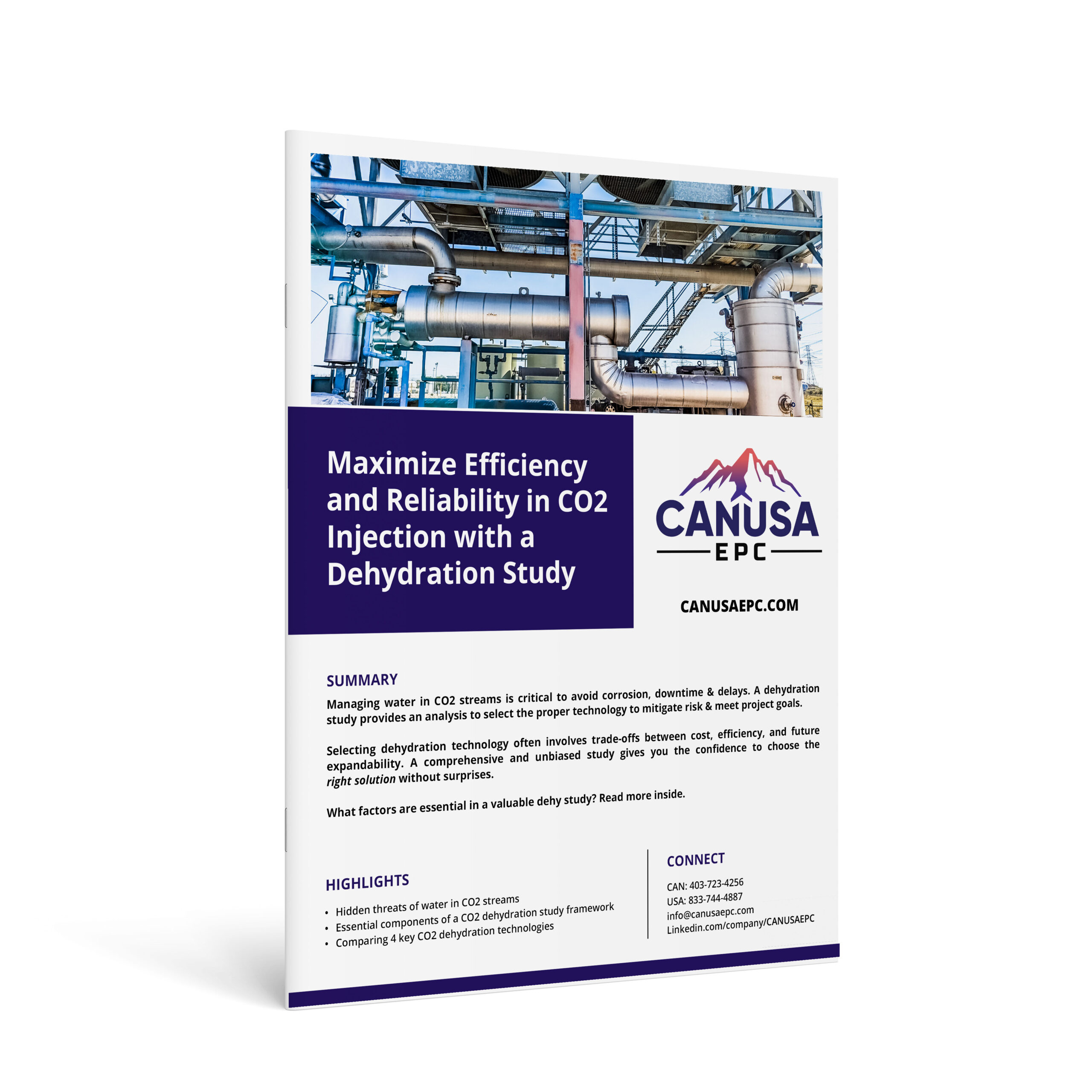
Managing water in CO2 streams is critical to avoid corrosion, downtime & delays. A dehydration study provides an analysis to select the proper technology to mitigate risk & meet project goals. Dehydration technology selection often involves trade-offs between cost, efficiency, and future expandability.
A comprehensive and unbiased study gives you the confidence to choose the right solution without surprises. What factors are essential in a valuable dehy study? Read more inside.
This guide includes:
Hidden threats of water in CO2 streams
Essential components of a CO2 dehydration study framework
Excess water in CO2 streams can lead to severe project risks, including equipment failure, blocked pipelines, and compromised system integrity. Without accurate data and a clear strategy, saturated CO2 can cause significant operating challenges. Technology selection during a CO2 injection project impacts profitability, safety, and longevity. A comprehensive CO2 dehydration study is the key to preventing these risks. It provides the clarity you need to make informed technology decisions, ensuring your operations remain safe, reliable and efficient.
The Hidden Threat of Water in CO2 Streams
Excess water in CO2 streams poses significant risks, including:
Pipeline Corrosion:
Water reacts with CO2 to form carbonic acid, which can rapidly erode infrastructure.
Hydrate Formation:
Under high-pressure conditions, water can crystallize, causing blockages that disrupt operations.
Reduced Injection Efficiency:
High water content undermines injection reliability, leading to expensive maintenance and unplanned downtime.
Water content targets typically range from 10 ppm to 50 lb/MMscf, depending on your transportation strategy, materials selection, and injection goals. For projects involving long pipelines or stringent injection requirements, managing water content isn’t optional—it’s essential.
Why a Dehydration Study Is Your Vital First Step
The right dehydration study transforms uncertainty into clarity. It will provide actionable insights to guide your project and give you confidence with decision-making.
Here’s how:
Define Project Objectives and Constraints:
Document your project’s goals, specifications, and concerns. A clear starting point ensures alignment across project teams.
Understand the Composition of your Gas Stream:
Analyze the composition of your CO2 stream, identifying contaminants that may affect dehydration technology performance.
Clear Evaluation of Dehydration Technology Options:
Compare technologies based on CapEx, OpEx, operability, and scalability. Focus on solutions that align with your team’s expertise and long-term project needs.
A Transparent and Unbiased Analysis:
Selecting dehydration technology often involve trade-offs between cost, efficiency, and future expandability. A comprehensive study gives you the confidence to choose the right solution without surprises.
Comparing CO2 Dehydration Technologies
Selecting the right technology depends on your project’s specific needs. A breakdown of common options is below:
Glycol Absorption Dehydration using Tri-Ethylene Glycol (TEG):
One of the most common technology suitable for many projects.
Requires additional modifications to achieve ultra-low water content.
Larger footprint and higher maintenance demands.
Desiccant Adsorption Systems:
Achieves extremely low water content, ideal for stringent requirements.
Higher upfront costs due to desiccant materials.
Ideal for projects with ultra-low water content targets.
Semi-Permeable Membranes:
Advanced systems offering high efficiency.
Require gas pre-treatment and higher inlet pressures, increasing upfront investment.
Ideal for projects needing minimal removal.
Chiller/Refrigeration Systems:
Uses dew point control to condense water from the vapor phase to a liquid.
Options like DEXPro leverage innovative solutions for energy-efficient cooling.
Effective for moderate water removal but with limitations on extreme requirements.
Real-World Success: Evaluation Findings for CO2 Dehydration
In a recent CO2 injection project, CANUSA EPC was asked to evaluate dehydration options for reducing water to a 25 lb limit in the gas stream prior to injection.
The framework of their evaluation can be considered a minimum viable standard for dehydration analysis.
Reliability
Uptime
CapEx and OpEx
Safety
Schedule Risk
Operability/Ease of Maintenance
Stakeholder Support
Environmental Impact
Expansion Potential
The following dehydration solutions were evaluated to determine which technology would best meet the client’s requirements:
In this client’s case, DEXPro stood out for its integration capabilities, environmental efficiency, and alignment with the client’s sustainability goals.
Download the Full Paper on CO2 Injection & Dehydration:
Access the comparison of key technologies presented in this article by downloading CANUSA EPC’s paper.
Embarking on a CO2 injection project without a dehydration study is like flying blind. Start with this critical step and ensure the dehydration study follows the framework within the paper – before assembling your project team.