Sebastian Jamili, Project Engineer I, CANUSA EPC
Reviewed by Brett Ingram, P.Eng, Director of Projects, Oil & Gas
Introduction
If your PVRVs keep lifting or your tanks are venting hydrocarbons, you already know there’s a problem. The harder question is where to fix it. Do you go upstream and stop the gas before it reaches the tanks, or do you capture what’s coming off the tanks?
This post is for operations, facilities, and emissions teams weighing that call. We’ll walk through the three tank emissions options we evaluated for a midstream operator at three gas plants in West Texas, why the client chose the one it did, and what to watch for when you add equipment to an existing tank system.
1. What Drives Tank Emissions at a Gas Plant
On this project, the tanks weren’t the root cause. They were just where the problem showed up.
During site visits, our team talked with the control room and operations. One of the closed drain separators upstream wasn’t getting enough residence time, and the closed drain system didn’t have the throughput the plant needed. That led to:
- High hydrocarbon content in the liquids reaching the tanks
- Gas flashing off once those liquids hit the tanks
- PVRVs and EPRVs venting to atmosphere
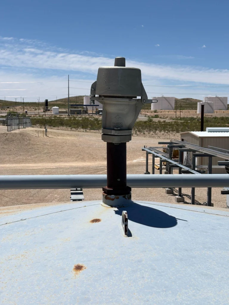
It’s a common pattern. When tanks vent, look at what’s feeding them before you decide what to add to them.
The regulatory pressure is real, too. Under EPA’s storage vessel rules (NSPS OOOOb), a new or modified tank battery with potential emissions of 6 tons per year of VOC or 20 tons per year of methane must cut those emissions by 95%.
2. Three Options to Reduce Tank Emissions
We evaluated three ways to solve the problem. Each one sits at a different point in the process.
| Option | What it does | Main trade-off |
|---|---|---|
| Upsize the closed drain separator | Removes hydrocarbons upstream, before they reach the tanks | Longest lead time and tie-in scope, likely tied to a turnaround |
| Vapor recovery unit (VRU) | Captures tank vapors and recovers them | Higher cost, long lead time, and significant power and I/O demand |
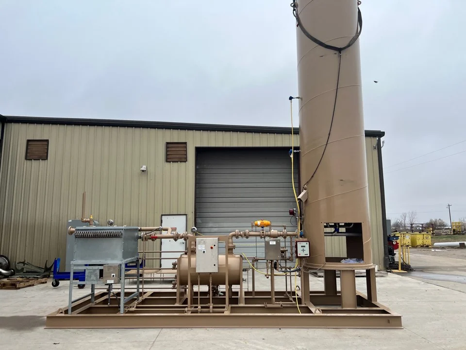
| Blower to flare header | Pulls tank vapors and sends them to the flare instead of atmosphere | Adds a new path into a low-pressure system that needs careful protection |
The separator upgrade treats the cause and has low operating costs. The VRU and the blower treat the symptoms and need power to run. On paper, the separator looks like the cleanest answer. On this project, it wasn’t the right one.
Comparing emissions projects across several facilities? See how we approach emissions reduction for oil and gas facilities.
3. Why a Blower to Flare Won This Time
The engineering logic pointed at the separator. The business constraints pointed at the blower. As Brett Ingram, P.Eng., put it, “this is backwards to how we initially started the project.”
Here’s what tipped the decision:
- Project ownership. The emissions team owned the project, not operations. Their mandate was the tanks, so the scope moved to the tanks.
- A turnaround that slipped. One site had a turnaround planned for October that moved to roughly February or March. Waiting for it to replace a separator wasn’t acceptable. A blower could tie in with far less downtime.
- Lead time and cost. Blower lead times were much more favorable than a VRU’s, and much faster than full detailed engineering on a new closed drain separator.
- Power and I/O. A 50 hp blower fit within the power and I/O available at the sites. A VRU didn’t at most of them.
The takeaway: the best technical answer isn’t always the right project answer. Ask early who owns the project and what deadline is driving it.
4. What to Watch for When Adding a Blower to an Existing Tank System
A blower to flare is a simple system, but it’s tying into equipment that’s easy to upset. These are the items our team spent the most time on.
Protecting a low pressure system
The flare header runs at nominally 5 to 15 psi. The tanks are near atmospheric. When you discharge into that header, you’re adding a new path for a process upset to reach the tanks.
- Consider every case, including backflow through the header
- Define the safety controls before the design is locked
- Run a PHA for each site. We ran three, one per plant, and each one shaped the protections and controls in the final design
Spacing and area classification
- Confirm whether the blower skid is Class I, Div 2 or Div 1
- Remember that heavier hydrocarbon gases can pool at grade inside tank containment
- Decide early whether the blower can sit inside containment, next to the tanks, or only outside
Electrical capacity
Check available power and spare I/O at the start. On this project, they decided between the VRU and the blower.
When you’re ready to test constraints like these before design locks in, read how we approach project definition for brownfield facilities.
5. Questions to Ask Before You Choose a Tank Emissions Solution
Keep this checklist handy for your next venting problem:
- What’s feeding the tanks, and is upstream separation working?
- Who owns the project: emissions or operations?
- When’s the next turnaround, and can the project wait for it?
- What are the lead times for each option?
- Is there spare power and I/O at the site?
- Has a PHA covered backflow and upset cases on the flare header?
- Where can new equipment sit, given area classification and containment?
Conclusion
Tank emissions are often a symptom of a problem further upstream. Fixing the cause is usually the cleaner engineering answer. But ownership, schedule, power, and lead time can point you toward capturing vapors at the tanks instead.
For this operator, a blower to flare gave three West Texas gas plants a path to stop venting without waiting on a turnaround that had already slipped.
Dealing with venting tanks or PVRVs that won’t stay seated? When you’re ready, talk to our team about comparing options for your facility before you commit to one.