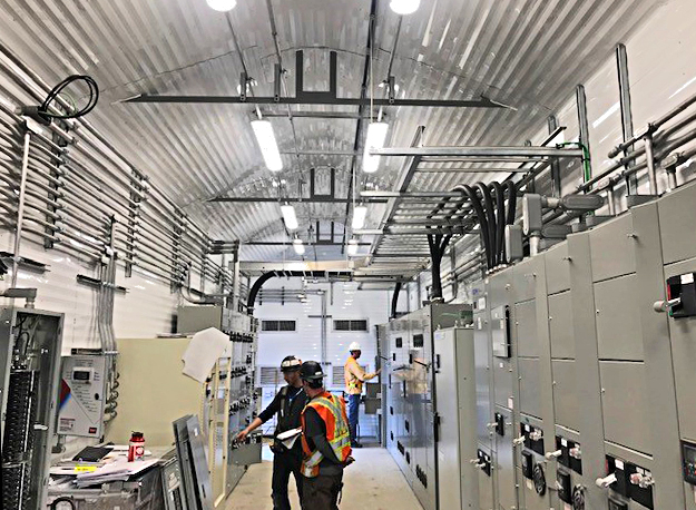
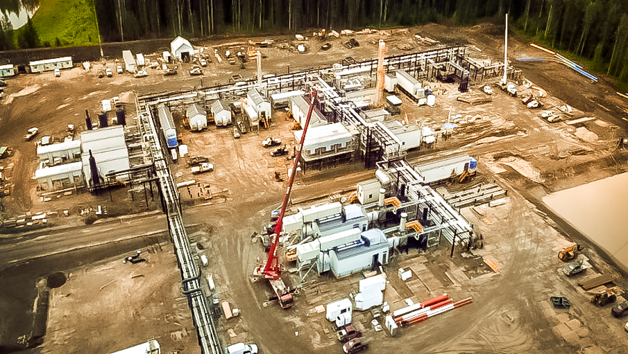
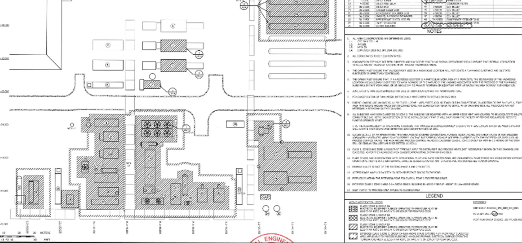
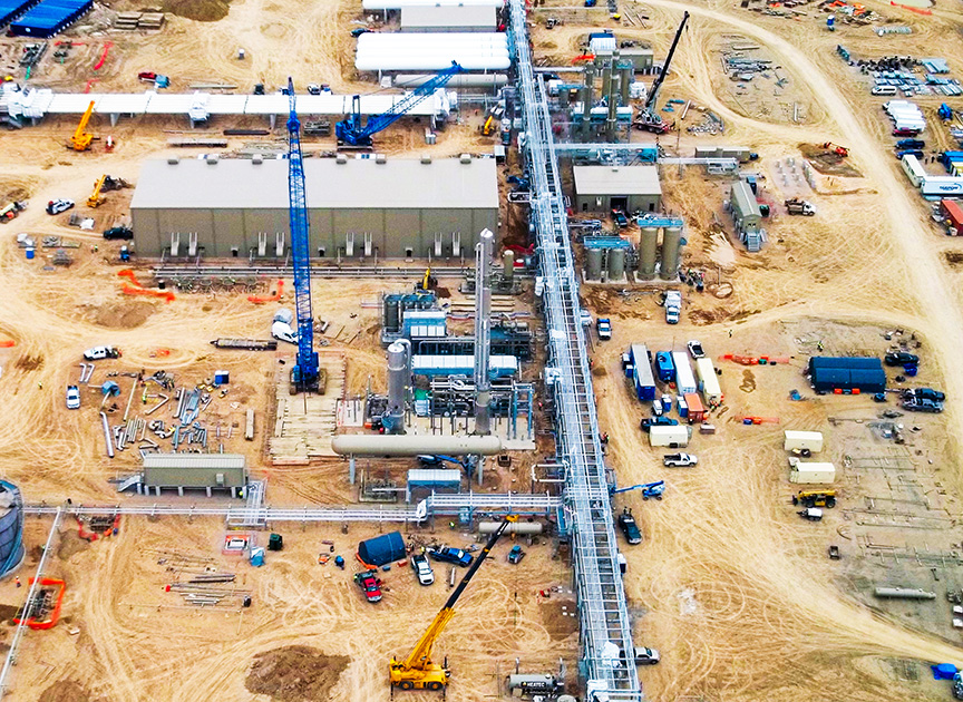
Our Midstream Client had an existing 180 MMSCFD gas processing facility and wanted to add another 400 MMSCFD processing equipment across two new processing trains. The new expansion was required to have its own inlet, flare, utilities and gas processing trains. There was a desire to leverage the existing site electrical and control systems for the expansion.
The Solution
Lump sum engineering
Lump sum DeltaV configuration and commissioning
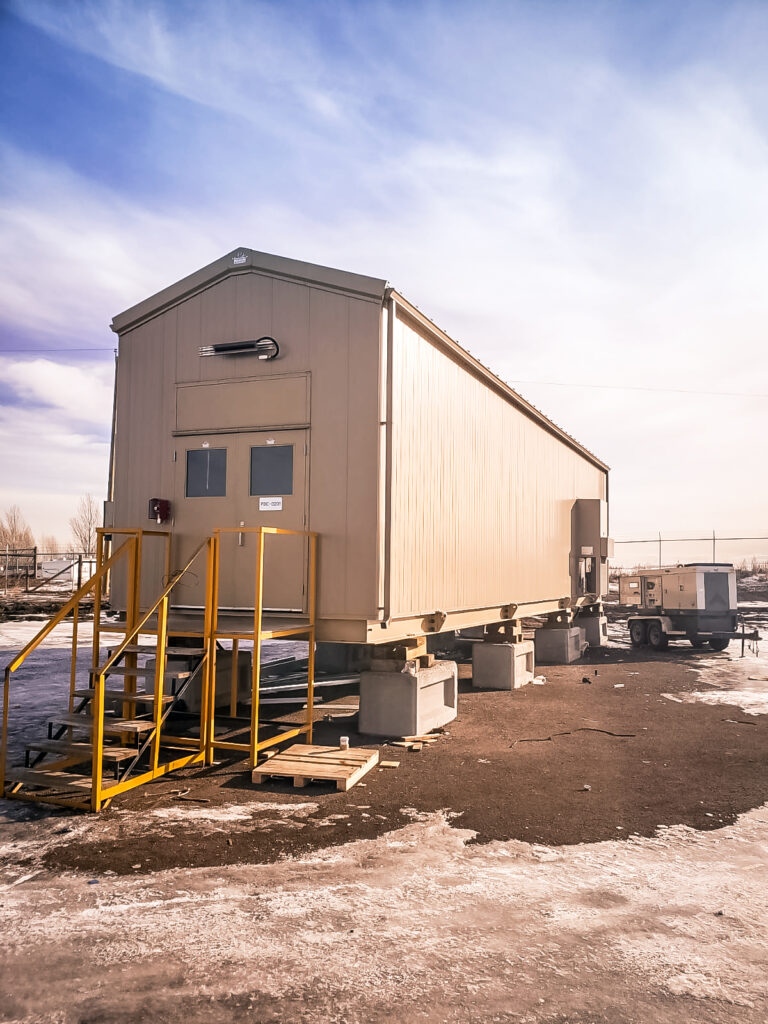
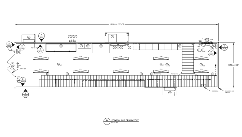
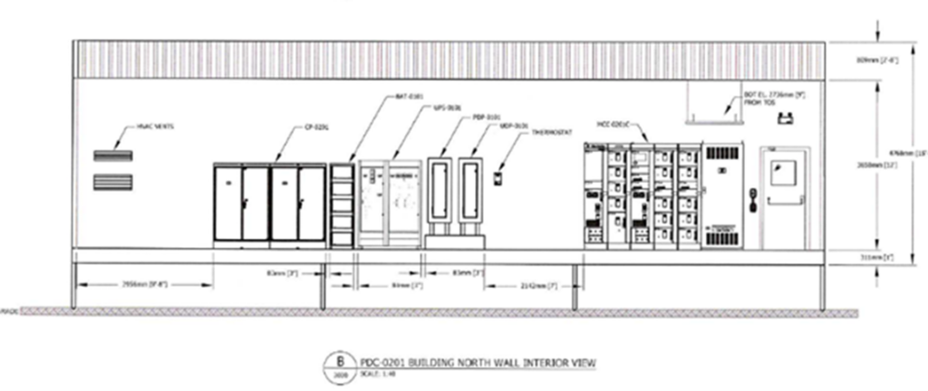
Lump sum supply of (4) PDC buildings including MV and LV electrical systems and control systems
DeltaV control cabinets and 9 RIO cabinets
Project included 14 MW of prime generations via solar turbines
1200 IO point systems
Integrated FAT testing in Calgary
On-site pre-commissioning and commissioning
The Results
Electrical packages arrived before the mechanical system
Lowered construction costs with a distributed network and electrical system
Developing industrial infrastructure projects is becoming more reliant on power planning and electrification of the future assets. Onsite power generation is becoming more attractive for operators to accelerate their project outside of utility timelines and control their long-term operating costs.
This whitepaper compiles data from previous projects and studies to support the financial analysis for power generation projects for operators determining what is the best onsite power solution for their project.
This power system planning guide includes:
CapEx and OpEx discussions for power generation
Reliability strategies for electrification of future facilities
Our Midstream Client required an electrical system consisting of medium and low voltage PDC buildings as part of their 200 MMSCF/day cryogenic facility which was executed as an EPC model with a large packager. There was a desire to provide an integrated motor control system with the site control platform, but also distribute the system to lower the total installed cost of the package.
The Solution
Designing for Construction:
Designing for Construction
The electrical system was designed to minimize cable runs by placing the buildings closer to the equipment
Distributing the electrical system into multiple buildings provided ease of transport and unloading and allowed for staged construction
Integration of the PDC and control system minimized onsite interconnects
Executing to Deliver on Cost & Schedule:
Structured a Lump sum supply of (4) PDC buildings including MV and LV systems and control systems to control costs
Selected sparing capacity on MCC lineups to accommodate changes from the process/mechanical team
Executed integrated testing before shipment to ensure minimal onsite changes
The Results
Low voltage buildings arrived before select mechanical packages allowing for electrical to execute in parallel to mechanical
Allowed for addition of VFDs from late changes to the design
CO2 capture and liquefaction is a process that converts gaseous carbon dioxide into liquid form, which can then be stored or transported for various applications. CO2 capture and liquefaction is an important technology for reducing greenhouse gas emissions and meeting lower carbon products. However, CO2 capture and liquefaction also require a significant amount of energy, especially for the compression of CO2 gas. Therefore, it is important pick the proper drive and compression technology to manage the “parasitic load” associated with processing the CO2.
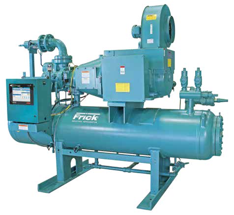
Screw compressors are widely used in CO2 liquefaction and capture facilities, as they can handle large volumes of gas and are common in refrigeration loops for the liquefaction process. Screw compressors typically use slide valves for unloading and capacity control, which adjust the internal volume of the compressor to match the process demand. However, using slide valves does not reduce the power requirements of the compressor as much as reducing the speed of the compressor would. Therefore, at reduced throughput, using variable frequency drives (VFDs) to control the speed of the screw compressors compared to slide valves provides lower energy usage.
Evaluating Screw Compression at CO2 Liquefaction Facility
In this analysis, we will present a case study of a 1000 metric ton per day (MTPD) CO2 liquefaction facility that used screw compression as the main driver and for cooling of the process. We will compare the performance and energy consumption of the screw compressors using slide valves and VFDs and show how VFDs can offer significant benefits in terms of:
efficiency,
reducing operating costs,
and providing a lower carbon intensity for the ethanol product.
We analyzed the data of a 1000 MTPD CO2 liquefaction facility that used electric driven screw compressors for the main compression and cooling stages of the process. The facility had a total of ~6500 kW of screw compressor load, consisting of three main compressors and 3 cooling compressors. The main compressors were designed to compress CO2 gas, and the cooling compressors were designed to provide refrigeration for the process.
Methodology: Comparing Slide Valves & VFDs
We compared the performance and energy consumption of the screw compressors using two different methods of capacity control: slide valves and VFDs.
Slide valves are mechanical devices that change the internal volume of the compressor by sliding a valve along the rotor, thus varying the amount of gas that enters the compression chamber.
VFDs are electronic devices that change the frequency and voltage of the electric supply to the compressor motor, thus varying the speed of the compressor.
We assumed that the facility is operating at 75% of its design capacity, which is a possible scenario for CO2 liquefaction and capture facilities based on the cycling that happens with fermentation.
We also estimated the capital cost and the operating cost of the screw compressors using slide valves and VFDs. For using slide valves, it was assumed that the compressors would be started with soft-starts. We assumed that the operating cost of the screw compressors was mainly determined by the electricity cost, which was $0.13 USD per kWh.
Results
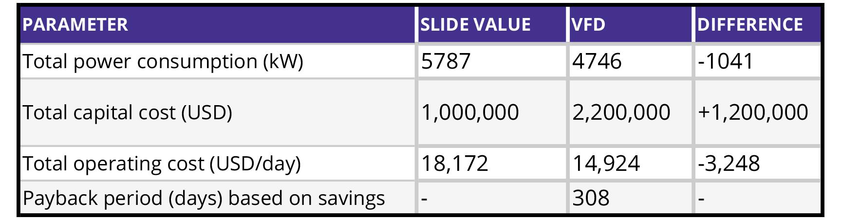
The results of our analysis are summarized in the table below.
As shown in the table, using VFDs to control the capacity of the screw compressors resulted in a 18% reduction in power consumption, compared to using slide valves. This translates to a 18% reduction in operating cost, which amounts to $3,248 USD per day in savings from lower power demands. On the other hand, using VFDs increased the capital cost of the screw compressors by 50%, which amounts to $1,000,000 USD.
Impact on Facility Profits
The results of our case study demonstrate that using VFDs to control the capacity of the screw compressors in CO2 liquefaction and capture facilities is economical if reduced capacity is anticipated. What determines the economics will be the duration of the reduced operations and the CO2e of the kWh.
Although VFDs have a higher capital cost than slide valves, the payback period of the VFDs is relatively short, as the operating cost savings are significant. Moreover, VFDs can help CO2 liquefaction and capture facilities achieve their environmental and social goals (45Z) as a low carbon fuel product, as they can reduce the greenhouse gas emissions and the energy intensity of the process.
Conclusion: VFDs Offer Significant Benefits
Are VFDs right for your facility? Using VFDs on screw compressors for CO2 liquefaction facilities can offer significant benefits in terms of efficiency and cost savings, compared to using slide valves. VFDs can reduce the power consumption and the operating cost of the screw compressors by 18%. In a reduced operating scenario of 75%, the payback period of the VFDs is only 308 days. Additional revenue increases can be recognized as well based on the CO2e of the kWh used in the liquefaction, as it will affect the multiplier of the government credits for 45Z.
Therefore, we recommend that when considering CO2 liquefaction, engineering should work to determine the anticipated average flow of CO2 product compared to the maximum capacity of the facility to determine the drive technology.
CANUSA EPC provides engineering, procurement, and construction management for CO2 liquefaction and capture facilities across North America. We focus on aligning the processing requirements with operational strategies to optimize your return on investment in these facilities. If you are interested, please contact us.