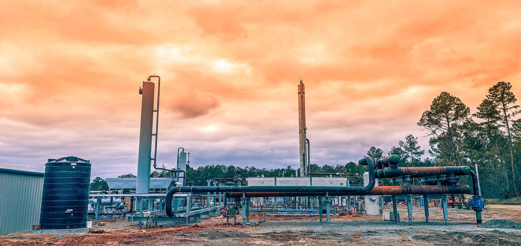
Industry: Natural Gas Processing

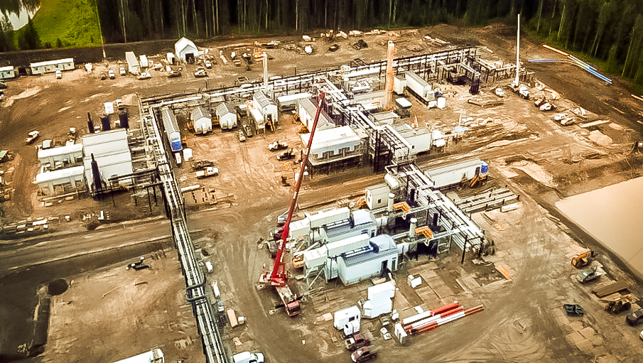
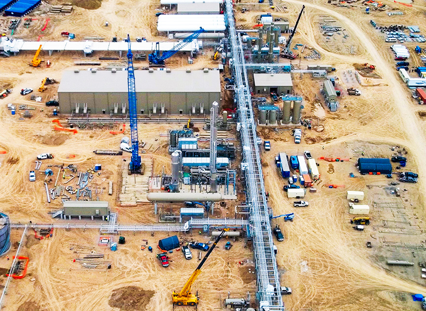
  • 200 MMSCFD System Expansion

    200 MMSCFD System Expansion

    The Challenge

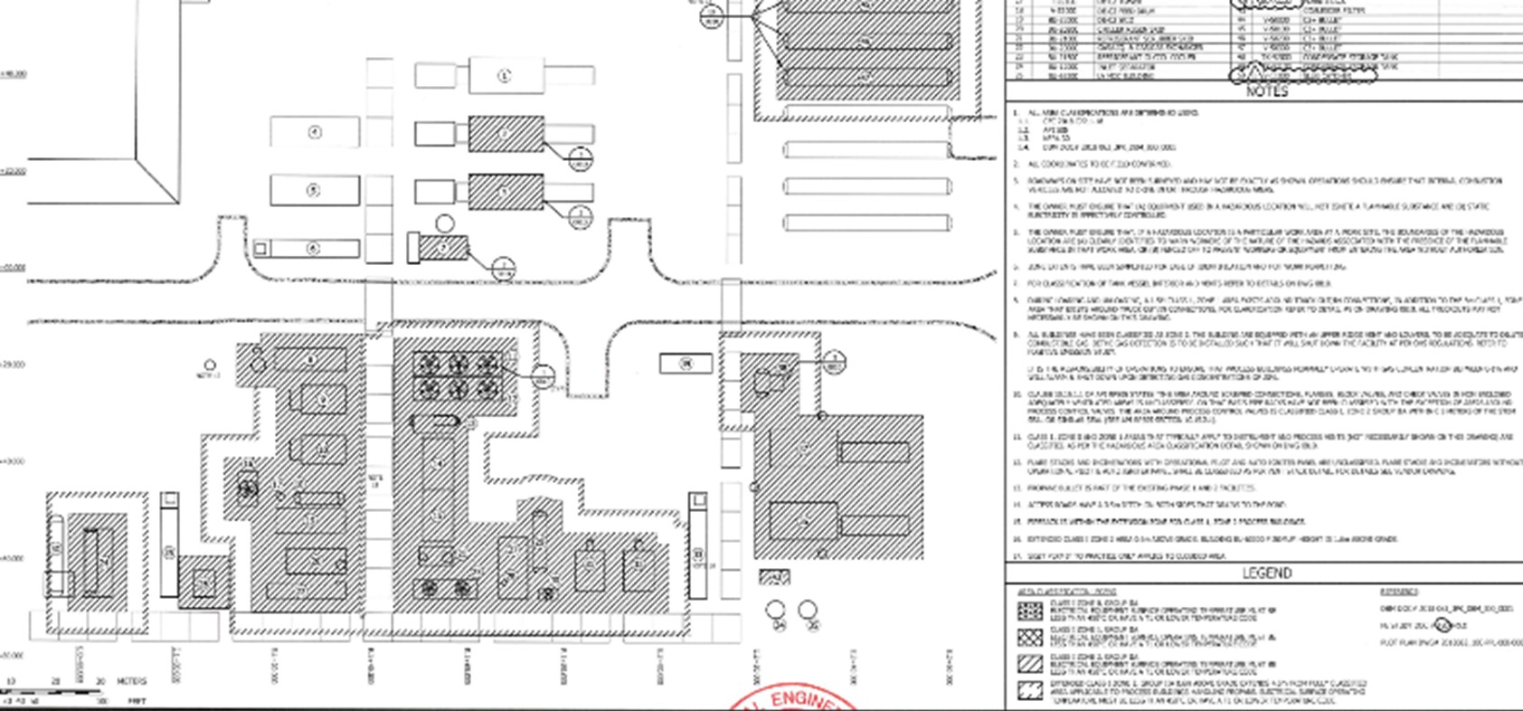
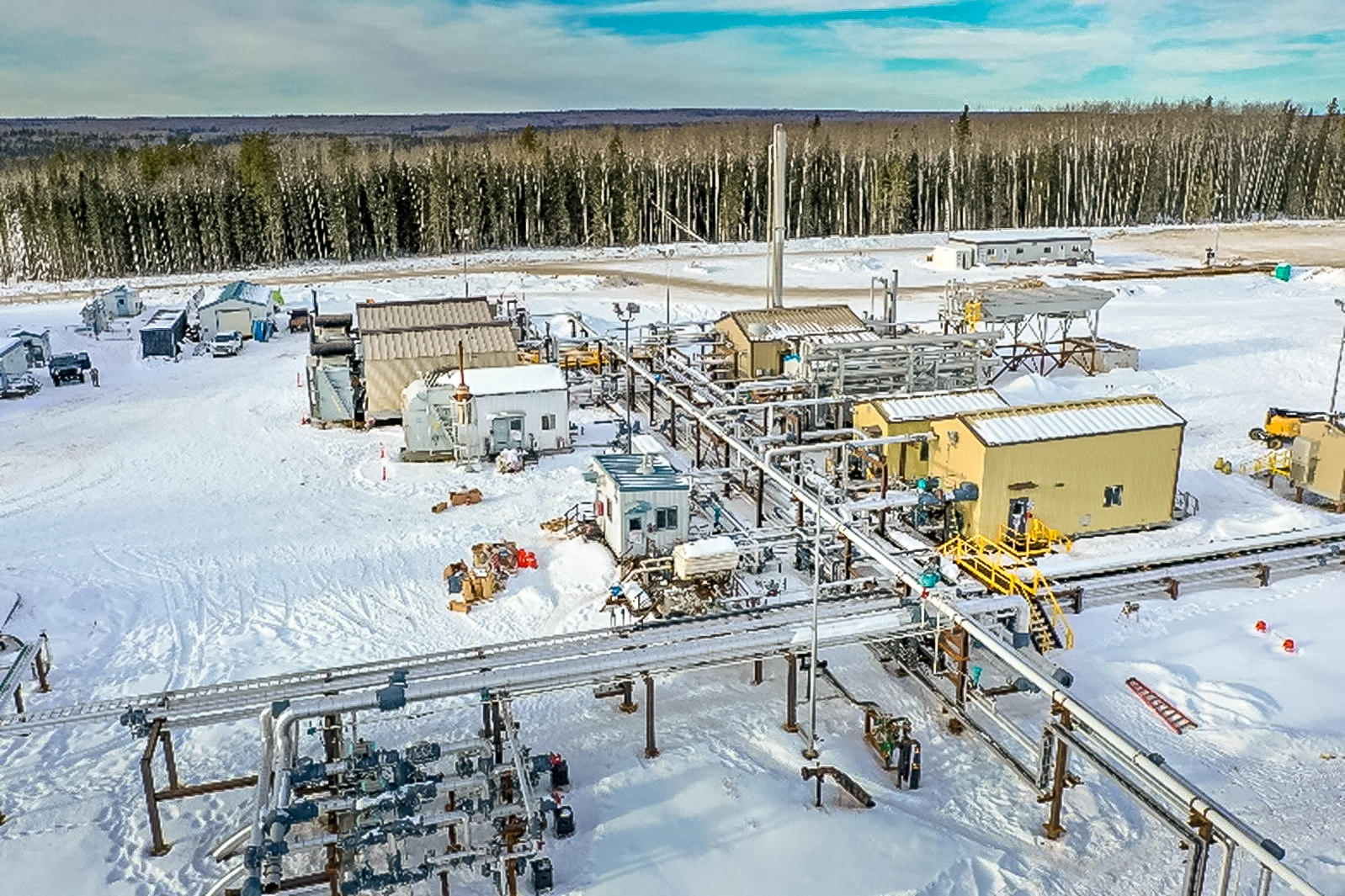
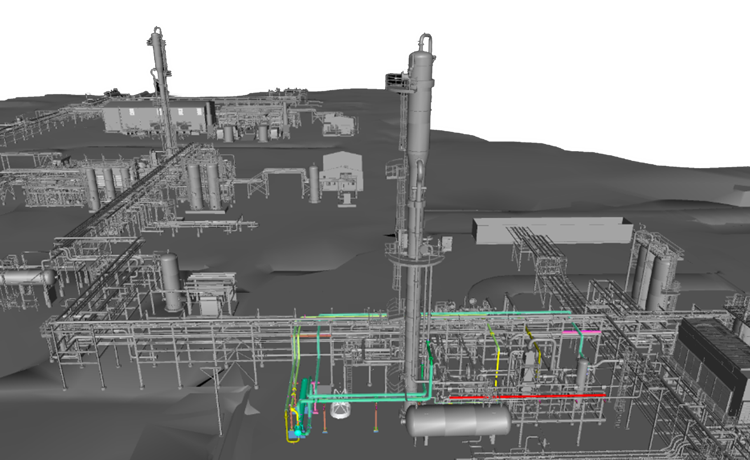
    Our Midstream Client had an existing 180 MMSCFD gas processing facility and wanted to add another 400 MMSCFD processing equipment across two new processing trains. The new expansion was required to have its own inlet, flare, utilities and gas processing trains. There was a desire to leverage the existing site electrical and control systems for the expansion.

    The Solution

    • Lump sum engineering
    • Lump sum DeltaV configuration and commissioning
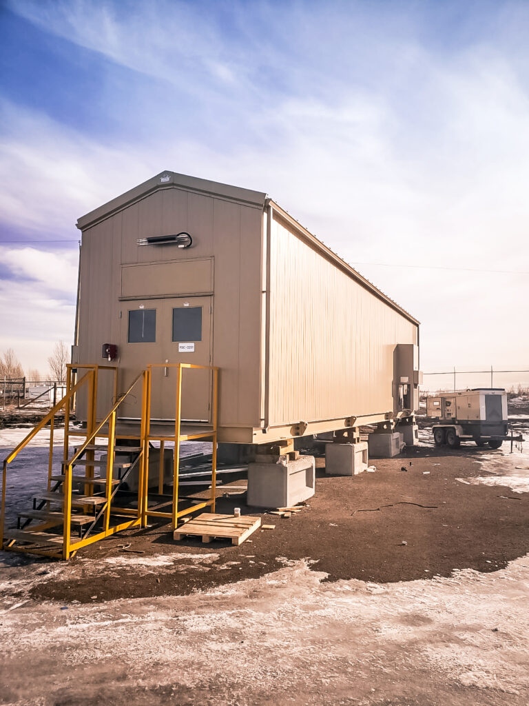
    • Lump sum supply of (4) PDC buildings including MV and LV electrical systems and control systems
    • DeltaV control cabinets and 9 RIO cabinets
    • Project included 14 MW of prime generations via solar turbines
    • 1200 IO point systems
    • Integrated FAT testing in Calgary
    • On-site pre-commissioning and commissioning

    The Results

    • Electrical packages arrived before the mechanical system
    • Lowered construction costs with a distributed network and electrical system
  • Power System Planning: Onsite Power System Considerations With Natural Gas

    Power System Planning: Onsite Power System Considerations With Natural Gas

    Summary

    Developing industrial infrastructure projects is becoming more reliant on power planning and electrification of the future assets. Onsite power generation is becoming more attractive for operators to accelerate their project outside of utility timelines and control their long-term operating costs.

    This whitepaper compiles data from previous projects and studies to support the financial analysis for power generation projects for operators determining what is the best onsite power solution for their project.

    This power system planning guide includes:

    • CapEx and OpEx discussions for power generation
    • Reliability strategies for electrification of future facilities
    • Analysis of modularized power deployments
  • LNG: Market Drivers & Technology Spotlight

    LNG: Market Drivers & Technology Spotlight

    Global energy demand is on the rise and LNG facilities are playing a bigger role than ever. LNG is a flexible, lower-emission fuel, and a way to transport and trade natural gas that was once landlocked by domestic demand. Natural gas demand is expected to grow 32% by 2050 with no peak in sight. This massive growth is driven by: 

    • Artificial intelligence 
    • Switch fuel  
    • Backup fuel, and 
    • Transport fuel. 

    Kindra Snow-McGregor, PE, from PetroSkills delivered a technical presentation for the WOGA (Women in Oil and Gas Association) April Technical Luncheon – “LNG Market Drivers & Technology”. Lila Salley attended and in this article she shares her key takeaways. 

    The North American market is rushing to build out LNG infrastructure, as shown in the figure below, to capture more of the international demand and there are numerous challenges. Understanding the market and project development landscape is critical if you want your LNG plans to run smoothly — and profitably.  

    Figure 1: Existing and under construction LNG facilities in North America (2016-2028) 

    Lila breaks down what Kindra shared about the current market considerations. 

    What is LNG and Why It Matters 

    LNG is natural gas cooled to -260°F to become a liquid, reducing its volume and then shipped at atmospheric pressure. This makes it far more efficient to store and transport — especially over long distances. In fact, LNG is more transportation-efficient than pipeline gas for distances over 1,500 miles and maintains its efficiency even up to 8,000 miles.  

    LNG Nominal Gas Transportation  

    Figure 2: Nominal natural gas transportation efficiency 

    LNG’s uses span across: 

    • Power generation and heating 
    • Transportation fuel 
    • Industrial heat source 
    • Chemical feedstock 

    LNG is emerging and North America is playing catch-up fast.  

    • We are projected to double LNG exports by 2028 
    • US produces 26% of international natural gas consumption demand 
    • 64% of US LNG exports went to Europe in 2024 

    LNG Liquefaction Facilities 

    The LNG market is hot, but that doesn’t make execution easy. Here are some of the biggest hurdles operators face today.

    1. LNG Facility Costs & Scale are Staggering

    Liquefaction facilities are capital-heavy: $1 billion per 1 million tonnes per year (mtpy) of capacity is the norm. A 5 mtpy plant, a mid-size operation, needs: 

    • 715 MMscfd of feed gas 
    • 302,000 horsepower in electricity 
    • 150 fin fan air-cooled exchangers 

    That’s before you factor in the 7–8% of gas burned internally just to run the plant.  

    Operator challenge: Building at scale while maintaining fuel efficiency and hitting commercial milestones. 

    2. Feed Gas Quality is a Hidden Risk 

    LNG specs are tight — especially around acid gas and mercury content. Many upstream sources don’t meet this standard without significant pretreatment. 

    Operator challenge: Designing flexible front-end systems to handle varying feedstock quality without ballooning costs. 

    3. US LNG Trading Long-Term vs. Spot Market 

    • Fixed fee of $2.25-3.50 per MMBtu is paid irrespective of lifted volume 
    • Shipping and re-gasification costs are covered by the buyer 
    • Trading driven by margin between Henry Hub price and regional spot market

    Operator challenge: Balancing long-term fixed fee structures with market uncertainty. 

    4. Technology Choice Can Make or Break ROI 

    • ConocoPhillips Optimized Cascade® is a process that utilizes pure propane, ethylene, and methane as refrigerants in a three-stage closed loop circuit. A heavies removal unit (HRU) and/or a nitrogen rejection unit (NRU) can be added to the LNG train depending on the feed composition and downstream requirements.  
    • APCI-C3MR includes a pre-treatment train to sweeten, dehydrate, and pre-cool the feed gas. Four stages of propane chilling are used to cool the mixed refrigerant which then enters a cryogenic heat exchanger to liquefy the pre-treated gas stream. 
    • Chart IPSMR™ technology utilizes a heavy hydrocarbon removal system to remove freezing components from the feed gas before liquefaction.  A single mixed refrigerant and a cold box comprised of brazed aluminum heat exchangers are then used to liquify the pre-treated gas stream.  

    Each has trade-offs in footprint, energy intensity, and startup cost. Choosing the wrong one can delay timelines or limit flexibility later.  

    If you are curious and would like to discuss these, connect with us. 

    Operator challenge: Matching process technology to project goals, gas characteristics, and long-term offtake strategy. 

    5. LNG Storage and Shipping 

    LNG fuelled vessels produce 23% less greenhouse gases. The typical LNG carrier size is 175,000m3, the scale of which can be seen in Figure 3 below. It’s cargo values between $21 to $39 million FOB. 

    Figure 3: LNG is pumped directly into the interior of the double hulled carrier for shipment. 

    Marine transport requires specialized LNG carriers, and receiving terminals must have the infrastructure for regasification, storage, and delivery. On land, LNG Virtual Pipelines are increasingly being used for off-grid power generation, truck refueling stations, and supplying gas to remote communities — all requiring small-scale storage hubs and flexible distribution networks. 

    Operator challenge: Designing for both large-scale export and decentralized delivery. As LNG applications diversify, infrastructure must be adaptable, scalable, and aligned with local demand — without driving up costs or complexity.

    6. European ESG Standards 

    The EU Methane Regulation was updated in August of 2024 and applies to both new and existing LNG supply contracts.  

    Importers are now required to submit details on methane measurement, reporting, and verification (MRV) methodologies from both the exporter and the producer, as well as methane intensity data. Importers must also take “all reasonable efforts” to ensure the MRV measures at the level of the producer are equivalent to those defined by the EU Methane Regulation.  

    Operator challenge: In the United States market, the importer often does not have a direct contractual relationship with the producer. It is important to be aware of this complexity in order to comply with the reporting requirements.  

    LNG Outlook for 2025 

    LNG operators who succeed will be the ones who design for variability, build for efficiency, and plan for volatility. 

    Kindra referenced the Shell LNG Outlook for 2025. It is a current resource with various tools for you to learn more about the current state of LNG – in-depth report, key facts and figures video, infographics and more.  

    The team at CANUSA found Kindra’s PetroSkills presentation incredibly valuable and extend appreciation to WOGA for hosting the event.  
  • Drivers of CO2 Dehydration

    Drivers of CO2 Dehydration

    Summary

    Concerned about water saturated CO2 causing reliability and integrity issues? Trying to determine the right dehydration technology for your CO2 injection project? Download the presentation CANUSA EPC’s Tevin Champagne delivered at the GPA Midstream 2025 Technical Conference.

    Content includes:

    • Understanding dehydration
    • Carbon capture process
    • Traditional dehydration approaches – TEG, chillers, DEXPro & others
    • Comparing dehydration technologies – reliability, CAPEX, OPEX, water content & environmental impact
  • NGL Fractionation Train

    NGL Fractionation Train

    The Challenge

    Development plans and contractual obligations required the Client to receive and process additional NGL volumes from truck-in through their existing fractionation process. This would allow the Client to capture the value of the fractionation products in the local market that would otherwise be passed down the value chain. The current process was limited in NGL storage volumes, tower capacities, re-boiler duties and product recoveries.

    The Solution

    CANUSA EPC provided, under a lump sum contract, value engineering and definition for the Client’s requirements.

    • Simulation through ProMax and utilized raw data to evaluate the sizes and internals of the current equipment
    • Completion of a What-If to assess the design impact of handling impurities (sour and water) on the front end
    • Operational improvements
    • Resolved DeC2 liquid level flooding
      ▪ De-bottlenecked DeC3 and DeC4 tower pressures
      ▪ Ensured product purities year-round
      ▪ Upgraded the storage area for increased volumes and trucking logistics
      ▪ Surge drum analysis to support inlet fluctuations
      ▪ Simplified product cooling design and controls
    • Procurement plan development to support budgeting
      ▪ Fractionation package
      ▪ NGL bullet, transfer pump skid and vapor return compressor
    • Repurpose of existing equipment to leverage in new design
      ▪ Heat medium exchange
      ▪ Fractionation coolers and reflux system
      ▪ Product storage and loadin

    The Results

    CANUSA EPC completed a capacity study and found a low-cost option that would provide for future expansion.

    • NGL fractionation capacity of 2,000 BPD with turndown to 240 BPD
    • TIC of $5MM for installation of the equipment
    • C3 and C4 product purities of 99%+
    • C5 product purity of 650 kg/m3 and 5% C4
    • Integration of 1 MMBTU/hr of waste heat to reduce OpEx as well as cooler and re-boiler duties
  • Natural Gas Processing Facility Alberta

    Natural Gas Processing Facility Alberta

    The Challenge

    Client directives for Environmental, Social, and Governance (ESG) in their development plans required that the increased oil production not require additional venting or flaring of associated gas. A feasibility design was required to determine the funding requirements to execute the project. The Client selected a brownfield sales metering station to convert a process plant capable of 20+ MMSCFD of gas and upgrade an adjacent oil treating facility to handle associated gas with their production plans.

    The Solution

    CANUSA EPC was contracted to offer Engineering, Procurement, and Construction Management (EPCM) services.

    • Procurement services to retrofit used and surplus equipment
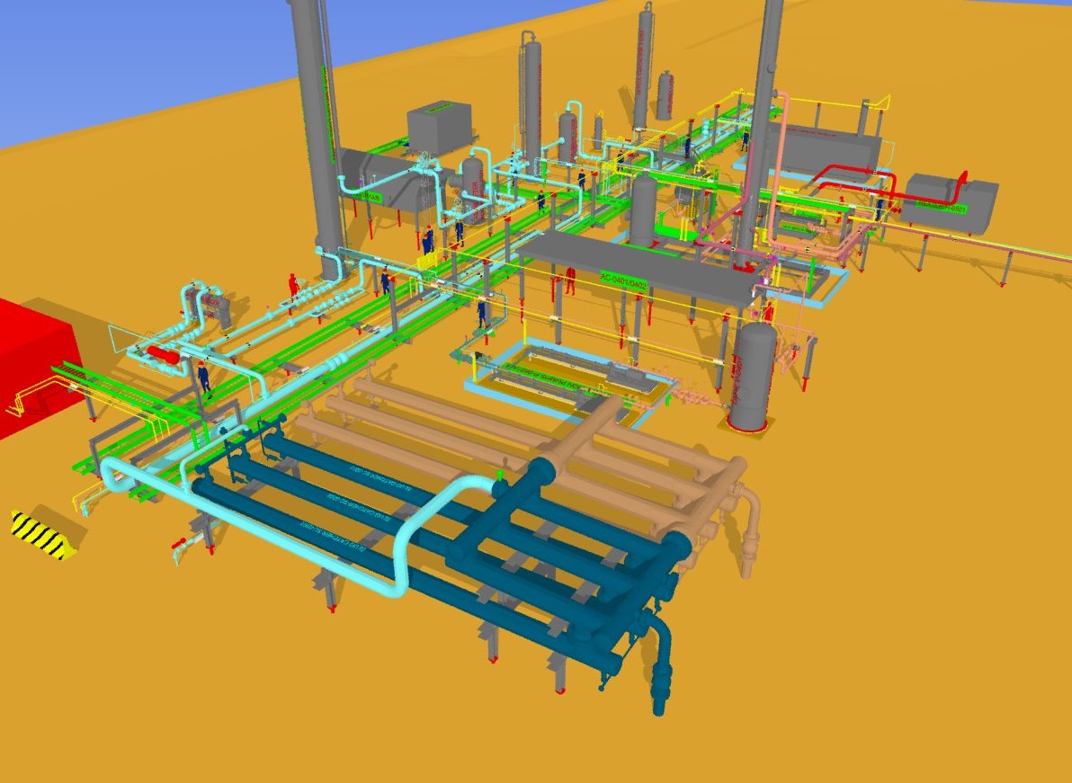
    • Developed a complete site model to accurately determine equipment requirements and weld inches
    • NGL handling and tie-in to existing oil battery
    • Deep Cut Refrigeration was selected for HCDP control
      • Designed and installation of a VRU to recover tank vapors
      • Added pipelines and liquid handling equipment including a treater
      • Explore options to utilize waste heat from cooling hot, treated oil
    • Designed a glycol waste heat system to offset heat trace loads

    The Results

    Lowered emissions of produced oil, meeting regulatory and client-mandated ESG commitments

    • Utilized 7 MMBTU/hr of waste heat
    • Added electrostatic treater to reduce energy requirements of treating the oil

    Executed TIC of $21MM for the gas plant project

    • Realized an additional 525+ bbl/d of NGL production
    • Realized $5MM+ in capital savings with surplus equipment

    Gas plant placed into operation within 8 months of EPCM Kick-Off Meeting

    Increased oil production by 7,000 BPD with the recovery of associated gas

  • Expandable Gas Treatment Facility

    Expandable Gas Treatment Facility

    The Challenge

    A new gas producer presented an opportunity for our Client to gather their gas. This gas required treatment before meeting pipeline sales gas specifications for the area. The producer insisted on a tight time frame for being ready to receive gas. Fortunately, our Client had idle equipment available for gas sweetening and gas dehydration at a site that was decommissioned. By using this existing equipment at the new site, up to 80 MMSCFD could be processed initially, plus future expansion capabilities up to a total of 200 MMSCFD.

    The Solution

    CANUSA EPC visited the decommissioned site to verify the available major equipment and understand the power and controls package.  Engineered valves and process piping that might be reused or refurbished were identified.

    Developing a Plan:

    • Evaluated the capacity of the existing amine treater package and dehydration equipment
    • Identified new equipment required for the balance of the facility
    • Developed design basis to capture required project technical requirements

    Sourcing New Equipment:

    • High-pressure inlet slug catcher
    • BTEX condenser and combustor
    • Storage tanks
    • Control room building and PLC

    Execute Value Engineering and Procurement to Accelerate the Project Schedule:

    • PSV calculations for, and safety review of, all existing and new equipment
    • Design of finger-type inlet slug catcher versus procurement of high-pressure vessel
    • Evaluate and recommend helical pile foundation deployment
    • Sourced major electrical tie-in equipment

    The Results

    • Deployed pile foundations to remove concrete cure time requirements from the construction schedule
    • Utility and electrical equipment sourced and removed from the critical path
    • Mechanical design allows for the future expansion of the facility throughput to 200 MMSCFD
  • Cryogenic Plant Optimization

    Cryogenic Plant Optimization

    The Challenge

    CANUSA EPC’s Client needed to determine the capability of throughput capacity for a dual-train plant related to rejection and recovery operations. Due to the minimum operating costs of the plant, the Client wanted to evaluate which major equipment could be upgraded to allow single or dual-train operations. Along with restriction conditions, the client desired to understand nameplate operating limits and applicable constraints.

    The Solution

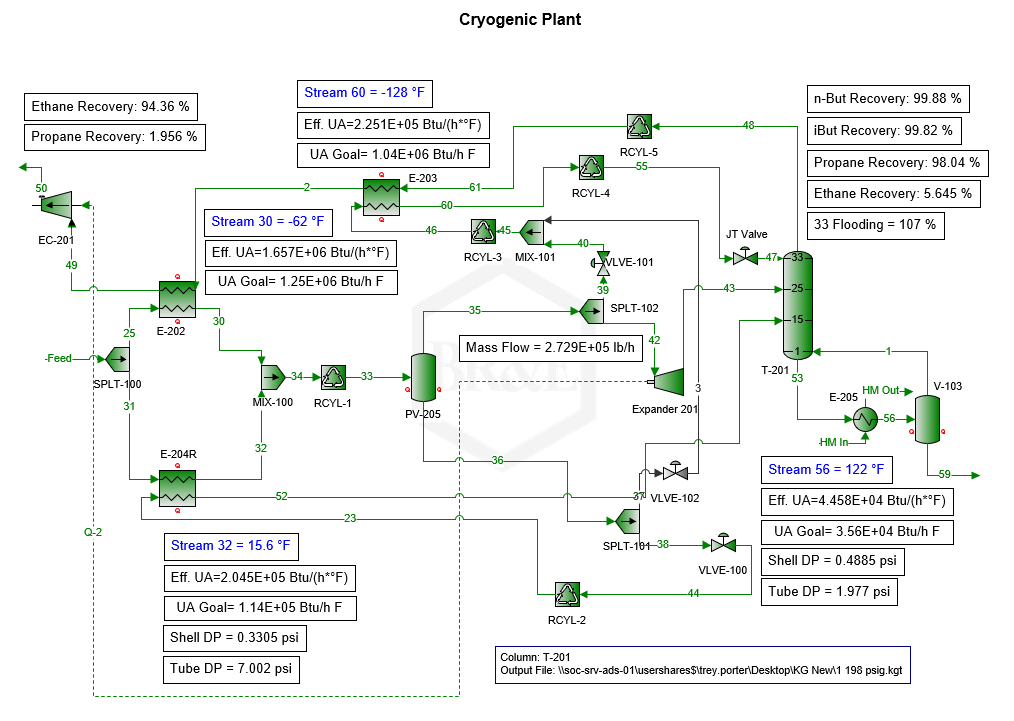
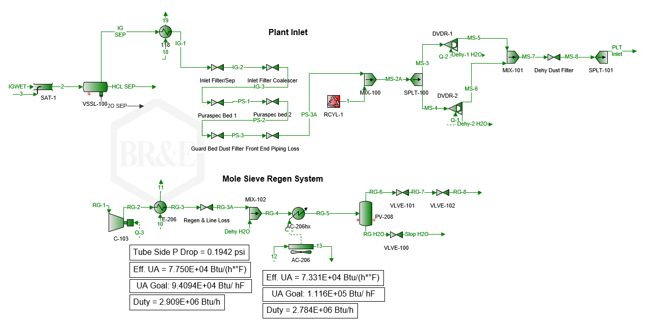
    CANUSA EPC conducted a debottlenecking study to evaluate throughput limiting conditions related to various operating limits for pieces of equipment like guard beds, mole sieves, heat exchangers, towers, etc. Along with equipment considerations, CANUSA EPC ran scenarios for the rejection and recovery operations.

    Process models of the major equipment in ProMax:

    • Modeled cryogenic process for rejection and recovery modes
    • Engaged vendors to determine plant inlet pressure drops through filters/guard beds
    • Simulated mole sieve regeneration/dehydration loops
    • Evaluated residue gas compression and heat content
    • Determined heat transfer properties for exchangers/aerial coolers

    Debottleneck Evaluation:

    • Evaluated key equipment results to remain within equipment limits
      • Tower flooding within KG Tower software
      • Convective heat transfer for heat exchangers and aerial coolers
      • Dehydration media, cycle times, and saturation for mole sieve units
      • NPSHa vs. NPSHr for product and heat-medium pumps
      • Mass flow for expander-compressors
      • Compressor HP and available head capabilities
    • Evaluated nozzle momentum with K-factors and pressure drops across all equipment
    • Evaluated liquid retention time and vapor entrainment for vessels
    • Evaluated the effect on recoveries as plant inlet flow increases

    The Results

    • Determined minimum requirements to increase the throughput of each train by 20 MMSCFD
    • Summarized for operations major equipment restrictions for both recovery and rejection modes
    • Worked with filter vendors to determine maximum operating limits based on filter components
  • Cryogenic Electrical System

    Cryogenic Electrical System

    The Challenge

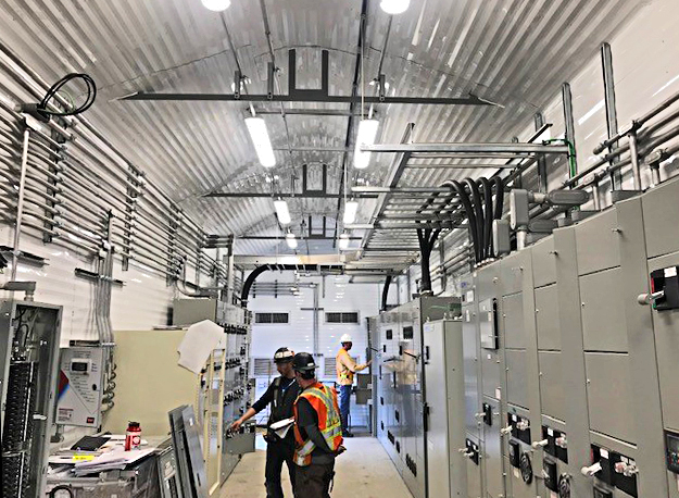
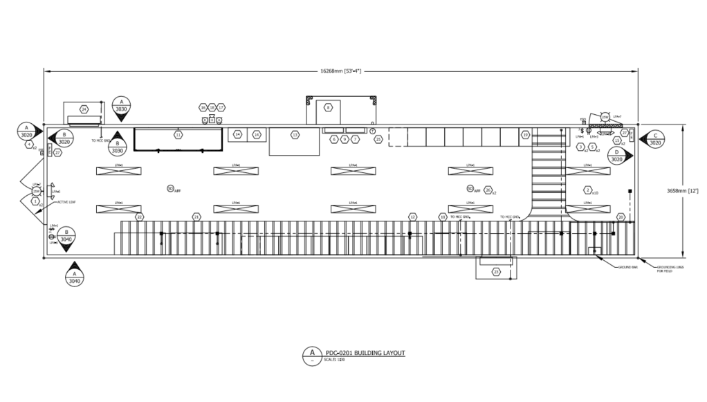
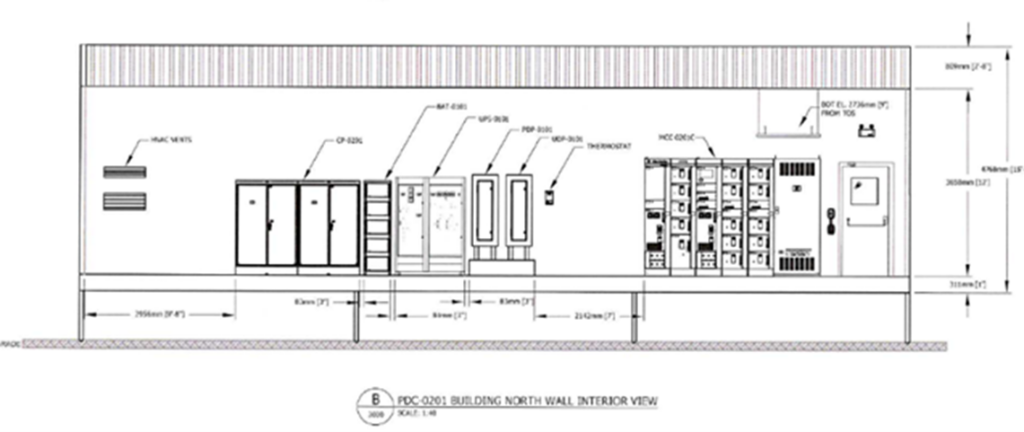
    Our Midstream Client required an electrical system consisting of medium and low voltage PDC buildings as part of their 200 MMSCF/day cryogenic facility which was executed as an EPC model with a large packager. There was a desire to provide an integrated motor control system with the site control platform, but also distribute the system to lower the total installed cost of the package.

    The Solution

    Designing for Construction:

    • Designing for Construction
      • The electrical system was designed to minimize cable runs by placing the buildings closer to the equipment
      • Distributing the electrical system into multiple buildings provided ease of transport and unloading and allowed for staged construction
      • Integration of the PDC and control system minimized onsite interconnects

    Executing to Deliver on Cost & Schedule:

    • Structured a Lump sum supply of (4) PDC buildings including MV and LV systems and control systems to control costs
    • Selected sparing capacity on MCC lineups to accommodate changes from the process/mechanical team
    • Executed integrated testing before shipment to ensure minimal onsite changes

    The Results

    • Low voltage buildings arrived before select mechanical packages allowing for electrical to execute in parallel to mechanical
    • Allowed for addition of VFDs from late changes to the design
    • Bottom entry connections lowered installation costs
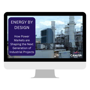
  • Energy By Design : How Power Markets Are Shaping the Next Generation of Industrial Projects

    Energy By Design : How Power Markets Are Shaping the Next Generation of Industrial Projects

    Summary

    Explore how surging U.S. electricity demand and record-breaking capacity market signals, like PJM’s $67 billion wake-up call, are reshaping the next generation of industrial energy infrastructure projects across North America. Examine key projects developing behind the meter facility and utility projects and the market forces driving unprecedented investment in onsite power generation, natural gas processing, and energy facility development. The Energy by Design presentation delivers actionable insights for energy professionals navigating the evolving power landscape.