As the Oil & Gas industry adapts to new environmental standards introduced through the EPA regulation OOOOb, operators are looking for low-emission substitutes for traditional instrument gas systems for pneumatic devices. Factors like power availability, extreme climates, retrofit feasibility, and long-term operating costs influence the most economical and technically viable instrument gas alternatives factor into the decision.
Although instrument air is a popular choice for pneumatic devices, there are a variety of instrument gas alternatives that are worth considering. These options include using liquid nitrogen tanks to supply gas to pneumatic devices, using electric actuators on valves, using a combustion-based or compressor-based vent capture system, and implementing low-emission alternatives to traditional pneumatic devices.
Controlling Instrument Gas Emissions
Natural gas-driven pneumatic devices have been the standard across upstream and midstream oil and gas sites for decades. These systems are simple, reliable, and easy to integrate, but they are a significant source of methane and VOC emissions in the oil and gas industry.
In the U.S., regulatory frameworks like EPA “OOOOb” (and soon, “OOOOc”) have required the transition away from traditional instrument gas systems. EPA Subpart OOOOb section 60.5390b requires operators to “design and operate each process controller affected facility with zero methane and VOC emissions to the atmosphere”, beginning January 22, 2027. The regulation includes mandatory monitoring and reporting for all facilities.
In Canada, producers are adopting emissions reduction strategies to align with both internal and external ESG targets, investor expectations, and net-zero commitments.
Controlling instrument gas emissions by implementing low-emission alternatives is the future of the industry.
The challenge? Each instrument gas alternative comes with its own trade-offs. Let’s evaluate!
Key Considerations
These three considerations often stall progress or lead to overbuilt systems that don’t actually meet site needs. These are the top 3 we see:
- Site Limitations
Power availability, space constraints, and environmental conditions will determine what is feasible.
- Budgeting & ROI
Every solution requires both CAPEX & OPEX. Liquid nitrogen systems, while low in initial cost, come with recurring delivery fees. Electric actuators are expensive, power-intensive, and, on existing sites, require retrofitting of every actuated valve.
- Technology Trade-offs
Each alternative has a unique set of pros and cons. Some offer zero emissions but require significant upfront investment. Others are easier to implement but come with ongoing operational costs or limited scalability.
Comparing the Top Alternatives for Traditional Instrument Gas Systems
Instrument Air Systems
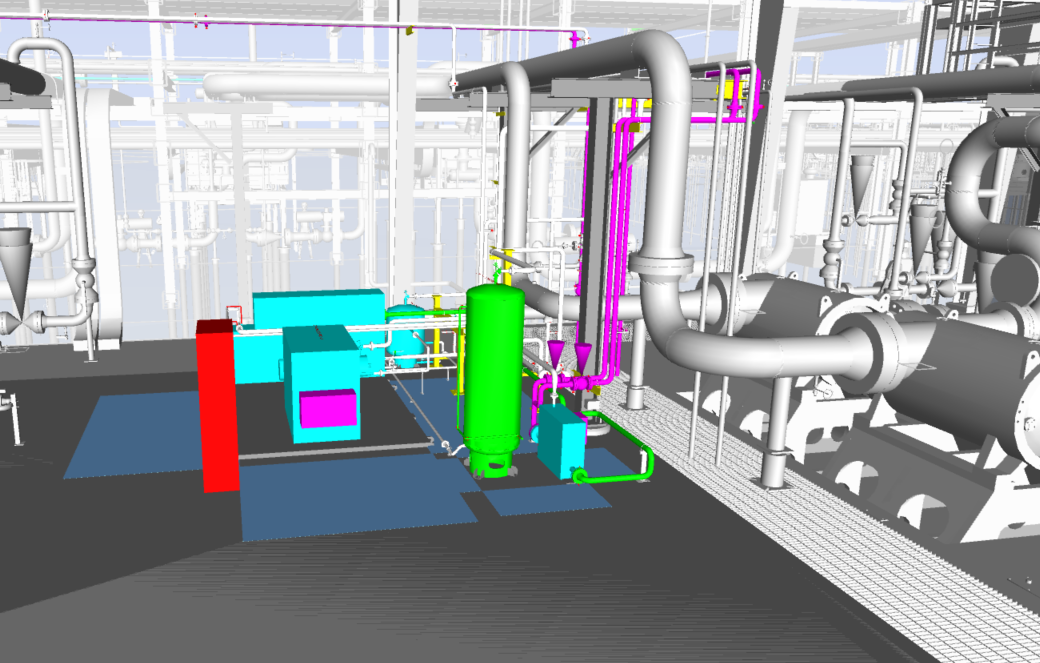
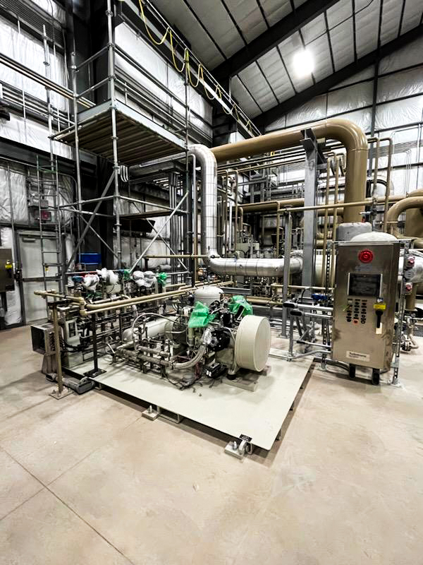
Instrument air is one of the most established alternatives to gas-driven pneumatics, particularly in midstream facilities. These systems use electric-driven compressors to deliver clean, dry air to valves and controllers, eliminating methane emissions entirely.
Pros:
- Easy integration
- Eliminates all process controller emissions – OOOO(b) compliant with no continued reporting
- Compatible with most existing pneumatic devices
- Product saved – no longer using sales gas to operate pneumatic devices
- Air is non-corrosive and abundant
- Expandable to pneumatic pumps and other emission reduction efforts (i.e. start air)
Cons:
- Introduces an additional piece of rotating equipment
- Requires power and space for compressors and dryers
- Higher upfront capital costs
- Possible rework of existing piping
- Introduces an oxidizer into pneumatic lines
- Increased operational effort due to required maintenance and troubleshooting
Best for: Midstream or central facilities with power availability.
Vendors Offering Compression: UECompression Packages
- 5 HP or 15 HP Reciprocating Packages
- Duplex Recip. Package
- 5 HP Rotary Scroll
- Custom Packages
Liquid Nitrogen Supply Systems
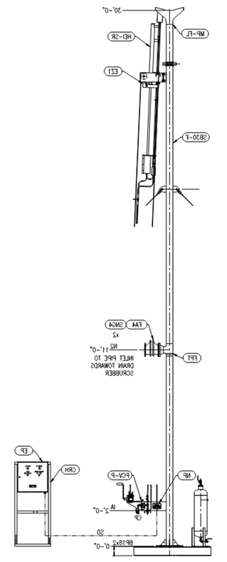
An option for remote or off-grid sites, liquid nitrogen provides a zero-emission, power-free alternative for driving pneumatic equipment. Suppliers deliver nitrogen in pressurized vessels, and nitrogen is passed through regulators to send vaporized nitrogen to drive pneumatic devices.
Pros:
- Easy integration
- Eliminates all process controller emissions – OOOO(b) compliant with no additional reporting
- Product saved – no longer using sales gas to operate pneumatic devices
- Pros over air – no additional rotating equipment
- Pros over gas – removes requirements for reporting to the EPA
- N2 is inert and does not provide an oxidizer into the process
- No additional power requirements
- Easily scalable & reliable
- No upfront capex requirements
- Minimal operator involvement
- Minimal seasonal, weather, or temperature implications
Cons:
- Requires regular nitrogen delivery (every 30–60 days) – adds to OPEX, delivery scheduling, risk of delays/impact to schedule
- Safety concerns with the addition of a pressurized vessel
- Not yet widely used, may face internal approval challenges
Best for: Small well pads or facilities without power infrastructure.
Vendors Offering Liquid Nitrogen Systems: Kathairos Solutions
- Provides services through the full timeline for integration, from site assessment to commissioning, monitoring, reporting, and operation.
Electric Valve Actuators
Electric actuators provide an emissions-free solution to control valve actuation, eliminating the need for access to pneumatic supply lines. They’re ideal for on/off valves in remote pipeline applications.
Pros:
- Emission-free
- Self-calibrating
- Low energy requirement
- Can be used in low temperature operation
- No need for routing of pneumatic lines
- Remote monitoring and configuration are available
- Solar-powered options are available – remote, power-free pipeline applications
Cons:
- Significant upfront capex – not realistic for large facilities with many actuated valves
- Slow response time – not suitable for tight process control
- Not suitable or realistic for existing facilities – requires significant modification to existing valves
- May not eliminate the need for pneumatic systems; other pneumatic signal users may exist apart from control valves
- Limited applicability as an emissions reduction technology in industry
- New technology – lack of familiarity or approval with clients and operators
- Although additional energy requirement and cable routing.
- Cannot operate on loss of power
Best for: Remote oil and gas sites with few pneumatic valves, and no additional pneumatic users.
Vendors Offering Electric Actuation: Emerson
- Varied applications suited for shut-down valves and control valves.
- Offering range of sizes and duty cycles.
Combustion-Based Vent Gas Capture
This strategy captures emissions from gas-driven pneumatics and routes them to a combustor, converting natural gas into CO₂. Although this method requires continued reporting with the EPA, it can offer OOOOb compliance with minimal disruption in operations.
Pros:
- Can continue to use instrument gas, no need to modify existing piping
- Eliminates need for additional rotating equipment, leading to equipment and operational savings
- Low initial Capex (if combustor is existing on site)
- No additional power requirements
- Possible tank battery applications – routing captured pneumatic emissions to tank venting header
Cons:
- Requires design and installation of a cover that can capture emissions from existing equipment
- Only realistic if there is an existing combustor that captured emissions can be routed to
- Significant engineering and design time
- Does not fully eliminate emissions from pneumatic devices. Monitoring and reporting are still required for OOOO(b) compliance
Best for: Facilities with an existing combustor and limited resources for a full system overhaul.
Capturing Compressor Emissions for Instrument Gas Use
This approach captures small amounts of vented gas from compressors and reuses it to power pneumatic devices. It’s a creative way to minimize waste and emissions using existing infrastructure.
Pros:
- Reduces total emissions from compressors
- Removes the need for header routing to compressors
- No additional power requirements
- Marginal increase in sales of gas
- OOOO(b) compliance for compressor emissions capture and process controllers
Cons:
- Significant engineering and design time, modification of on-skid piping
- Does not fully eliminate emissions from pneumatic devices. Monitoring and reporting are still required for OOOO(b) compliance.
Best for: Sites looking to improve compressor efficiency or reduce emissions without installing new systems.
Which Pneumatic Emissions Reduction Technology is Best?
There are numerous technologies available to reduce or eliminate emissions from instrument gas lines, whether it be implementing solutions within an existing instrument gas system, adopting instrument air or vaporized nitrogen, or utilizing electrically actuated valves. Although instrument air has been the most widely used pneumatic signal alternative within the industry, operators should understand that other technologies exist and may be a more practical solution for eliminating instrument gas emissions.
The technologies available allow for flexibility in a wide range of applications. There are options for sites with limited power availability, existing facilities looking to retrofit or upgrade their traditional instrument gas system, remote pipeline operations, and new facilities looking to build out with an emissions-free pneumatic system.
At CANUSA EPC, we help operators make informed decisions based on real-world experience. We’ve seen the nuances of site power, valve density, weather risk, and regulatory targets.
When you’re ready to talk instrumentation upgrades or emissions strategies, we’d be happy to share what’s working in the field.
__________
FURTHER EMISSIONS-REDUCTION READING
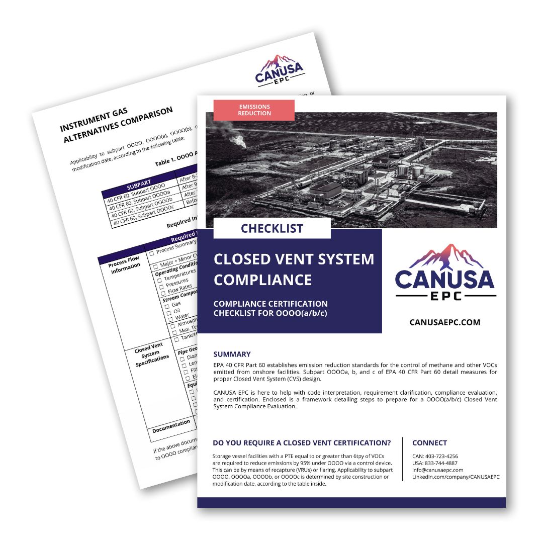
Instrument Gas Alternatives Comparison Guide
To accompany this blog, we have created a free comparison guide for your convenience. Download the Instrument Gas Alternatives Comparison Guide.
OOOO(b) for Compression Sites: Cost-Management Strategies for Methane Reduction
Want to ensure you meet budget and timelines? Read on for 7 strategies to consider.
__________
Author(s)
Megan Hurley, Engineer I
External Sources
- https://www.epa.gov/natural-gas-star-program/rulemakings-policy-and-laws-address-methane-emissions-oil-and-gas-sector#:~:text=Methane%20Emissions%20Standards,-Final%20Rules%20to&text=In%202024%2C%20EPA%20issued%20a,methane%20emissions%20from%20existing%20sources.&text=In%202016%20%2D%20EPA%20issued%20three,permitting%20requirements%20for%20the%20industry.
- eCFR :: 40 CFR Part 60 Subpart OOOOb — Standards of Performance for Crude Oil and Natural Gas Facilities for Which Construction, Modification or Reconstruction Commenced After December 6, 2022
- https://www.canada.ca/en/services/environment/weather/climatechange/climate-plan/2035-emissions-reduction-target.html