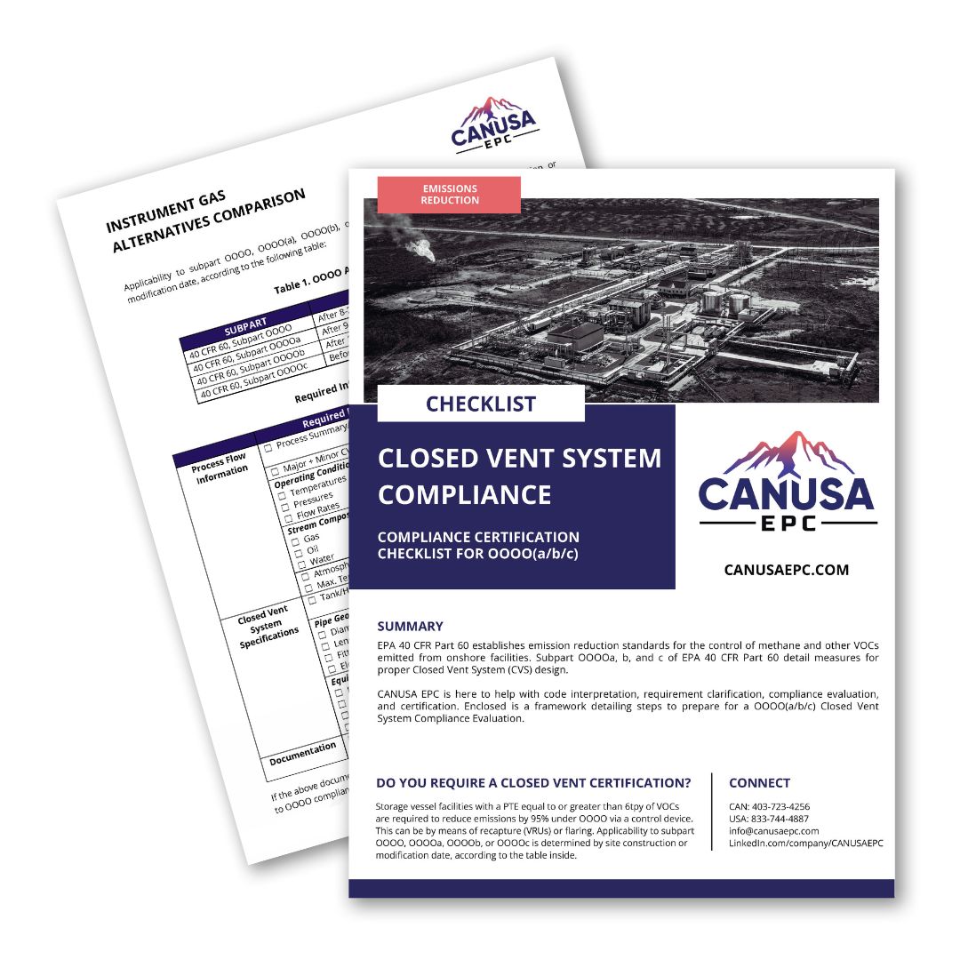
EPA 40 CFR Part 60 establishes emission reduction standards for the control of methane and other VOCs emitted from onshore facilities. Subpart OOOO(a/b/c) of EPA 40 CFR Part 60 detail measures for proper Closed Vent System (CVS) design.
CANUSA EPC is here to help with code interpretation, requirement clarification, compliance evaluation, and certification. Enclosed is a framework detailing steps to prepare for a OOOO(a/b/c) Closed Vent System Compliance Evaluation.
The EPA’s latest methane rule – OOOO(b) – mandates zero-emission process controllers and pneumatic pumps, pushing gas compression facilities to invest in compliance projects. Want to ensure you meet budget and timelines? Read on for 7 strategies to consider in your compliance project program.
This whitepaper compiles data from previous projects and studies to support the financial analysis for power generation projects for operators determining what is the best onsite power solution for their project.
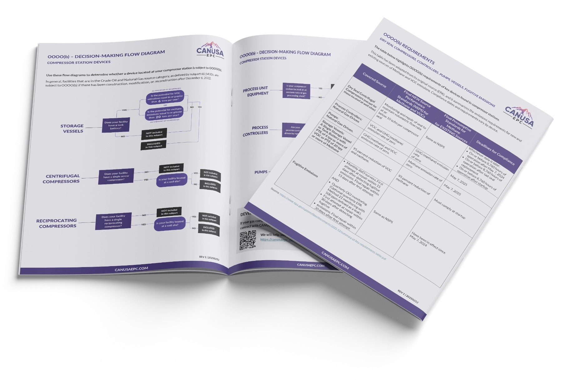
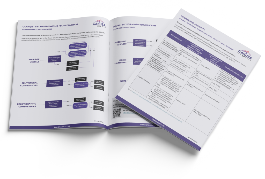
This OOOO(b) for compression sites guide includes:
Article, published in Hart Energy Magazine, discussing instrument air conversions, OOOO(b) planning and best practices, achieving operational efficiencies, and moving forward with compliance
Matrix highlighting OOOO(b) requirements of key devices found in compressor stations: dry seal compressors, controllers, pumps, vessels, and fugitive emissions
Decision-making flow diagrams to help you determine which OOOO(b) sub-parts pertain to your operation
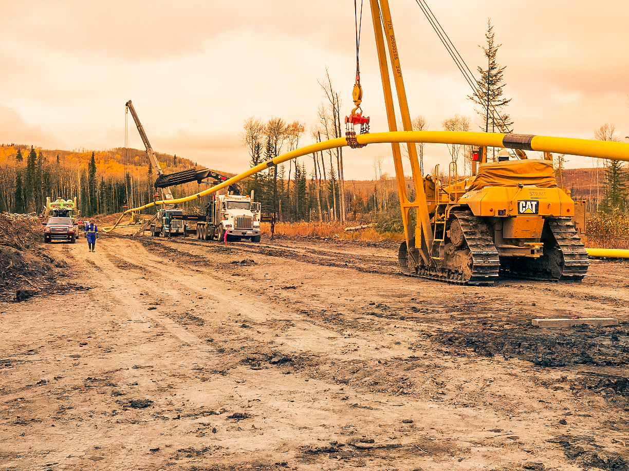
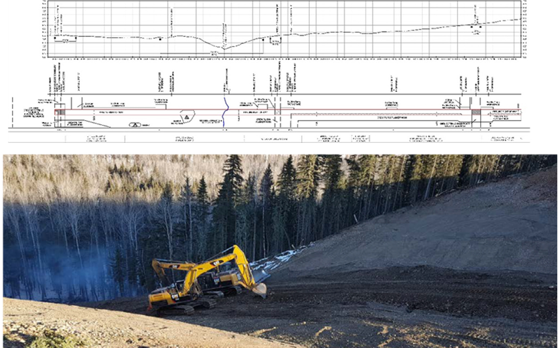
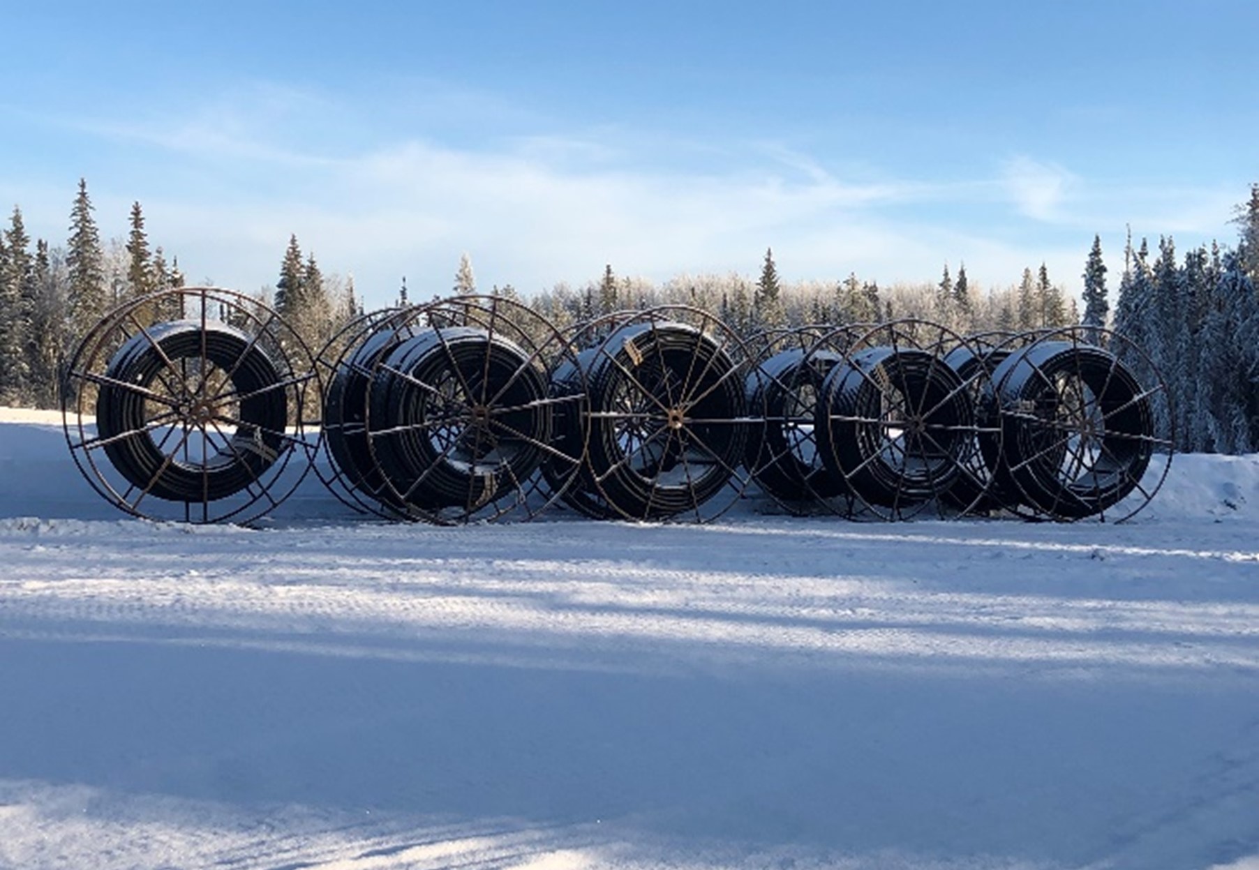
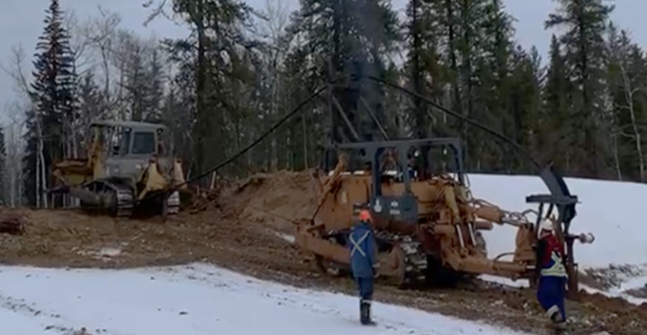
British Columbia has stringent pipeline regulations and the geography presents harsh weather and steep/diverse terrain. Due to the project’s construction size, nearly 60 vendors were required over the 10+ month schedule. With various constructability issues, especially pertaining to hydrotesting, de-watering and purging operations, the Client required a team with experience and the right tools to complete the project.
The Solution
CANUSA EPC provided a single point of contact for all 59 vendors
Designed and coordinated to safely cross large rivers while meeting all environmental regulations
Septimus NPS 8 sales gas and gathering pipeline loop (combined 9,800+ meters; river crossings)
Monias NPS 12 sales gas, NPS 6 natural gas and NPS 6 liquid pipeline constructions (combined 55,600+ meters)
Saturn NPS 16 sales gas pipeline construction (combined 23,900+ meters; river crossings)
Design of the pipeline pigging facilities for 900 ANSI system under CSA specifications
Daily, weekly and monthly project reporting including budget, schedule, safety and quality
Sweet natural gas and condensate pipelines were constructed as spare bi-directional lines for future production
The Results
Improved capacity and flexibility of the gathering and sales pipeline system
NPS 16 sales gas pipeline connected the NPS 12 pipeline from existing gas plant
Transported sweet natural gas from the field to the existing gas plant – allowing for incremental gas production
Provided flexibility for Client logistics with bi-directional designs
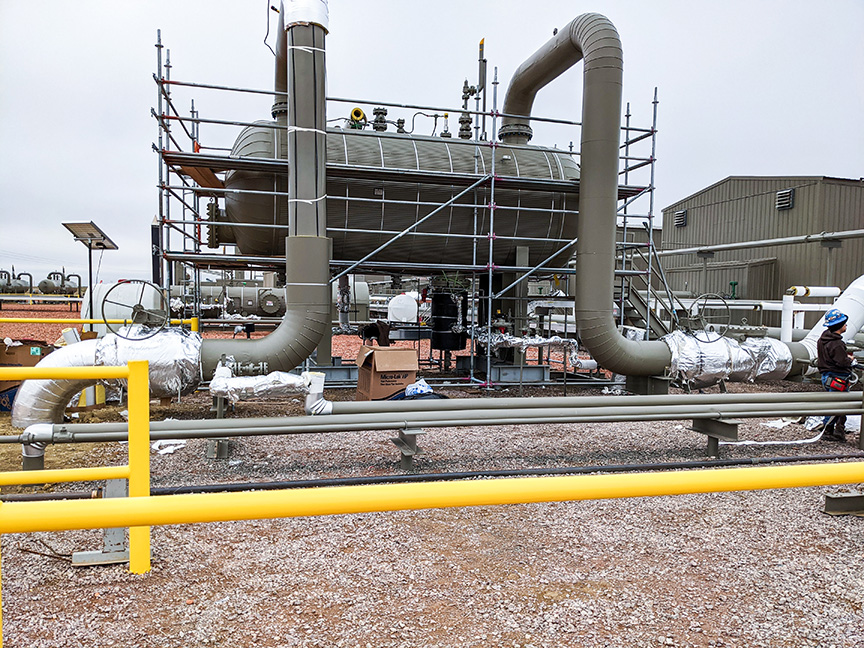
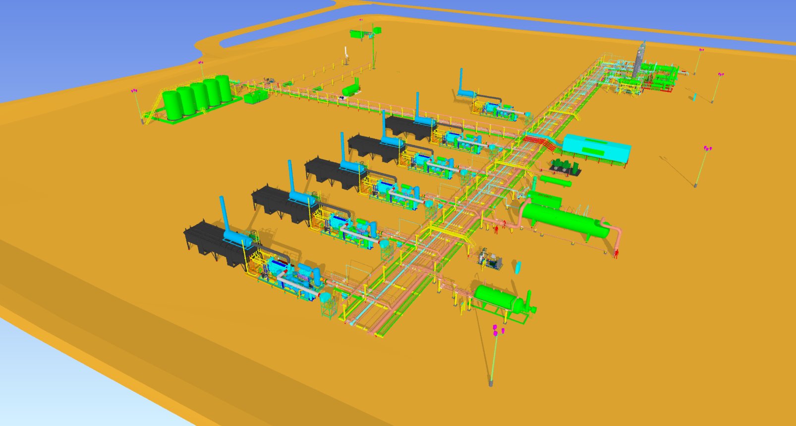
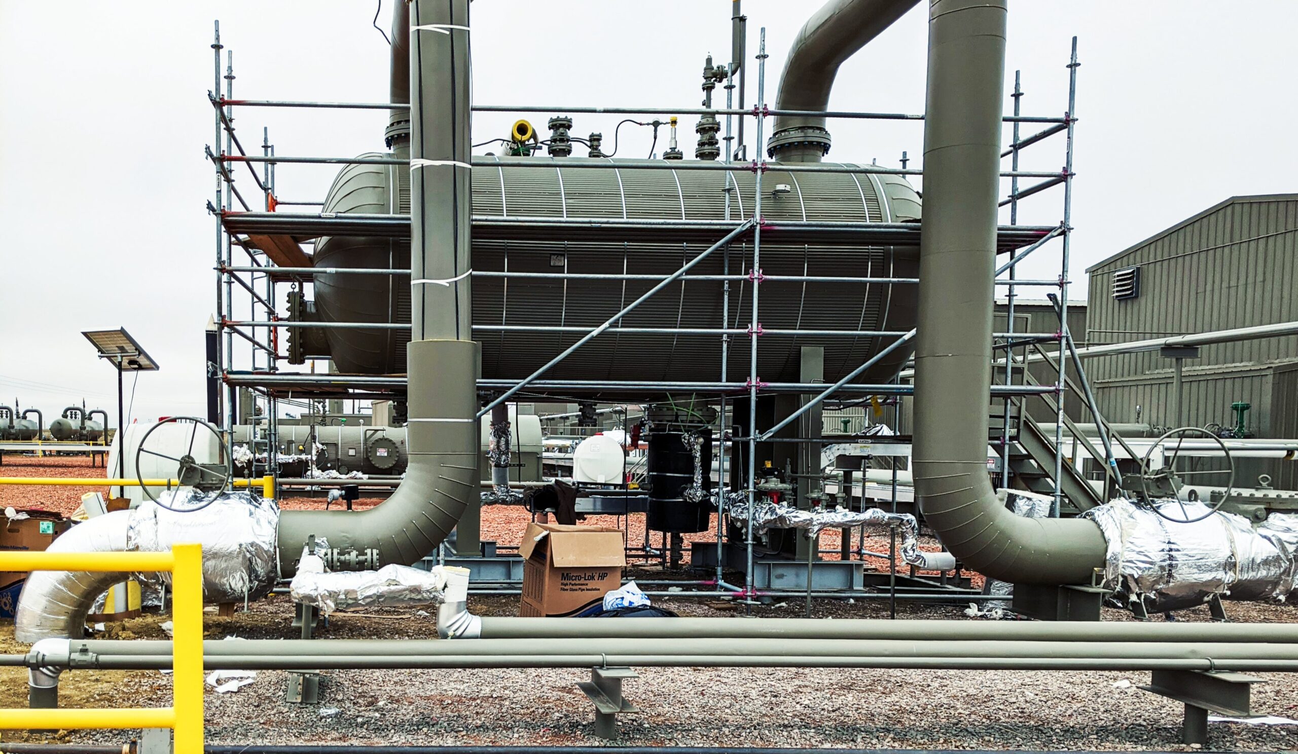
Growing gas production necessitated our client expand one of their compressor stations, doubling the capacity and total installed horsepower. The original design of the low-pressure inlet was originally designed for two slug catchers, leading to concern over liquid management onsite. The high-pressure inlet did not allow for blending for dehydration optimization. Late into execution of the project, the existing high-pressure 3-phase separator was upsized to improve liquid removal and dehydration performance.
The Solution
Developed a plan and budget:
Executed onsite visits and as-built documentation of existing facility
Reviewed operational improvements for the expansion
Developed design basis to capture required project technical requirements
Source new equipment:
Low-pressure inlet slug catcher
High-pressure 3-phase separator
Motor Control Center (MCC) expansion
Execute value engineering to support the project schedule:
P&ID generation
Equipment evaluation
PSV sizing calculations and safety review
Engineered valve specification
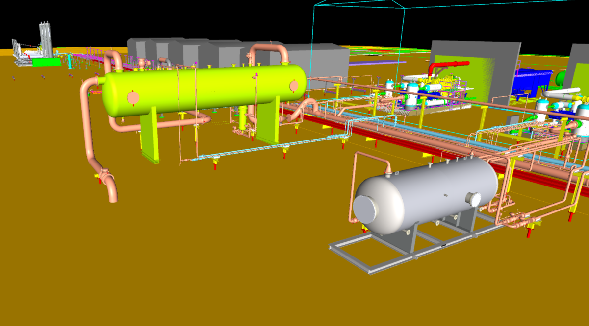
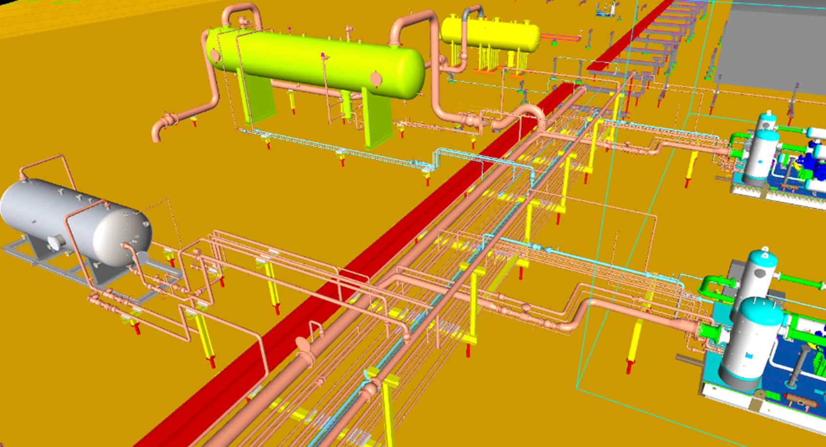
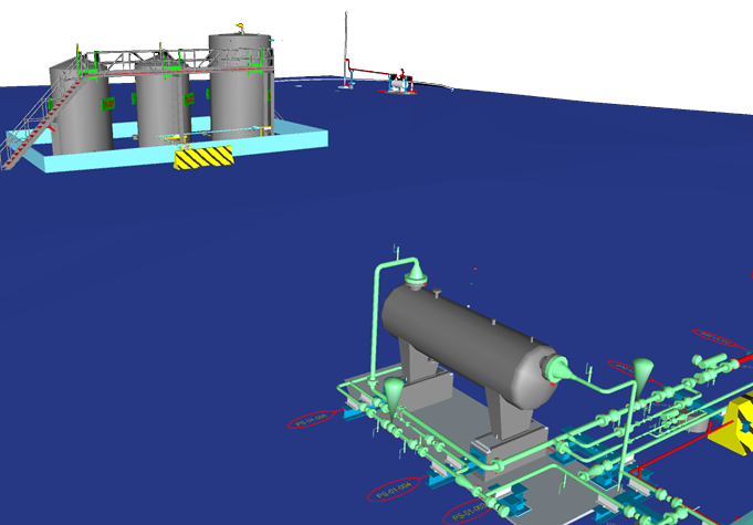
3D modeling
Construction packages for electrical, mechanical, and civil bids
The Results
Engineering:
Up-to-date engineering package for the site
Future compressor additions require no additional mechanical design
Developed plan for short shutdown window for tie-ins
Operations:
Addressed issues with high-pressure drains to VRU
Improved isolation and access to compressor packages
Consolidated planned equipment for a two-inlet design to single inlet
Additional gas production in the basin required our client to build a new compressor station, doubling the client’s compression capacity in the area from 120 MMscfd to 240 MMscfd. Due to the increasing CO2 content of the gas in the basin, the new station needed to include future Amine gas treatment in addition to gas dehydration. Functionality for gas blending from other high-pressure inlet sources with the sales gas was required to meet CO2 content and sales gas specifications in the short term. The client also wanted functionality to be able to combine low-pressure and high-pressure liquid products through a single sales pipeline.
The Solution
CANUSA EPC provided full discipline engineering to develop the construction packages for the client.
Developing a Plan to Meet Client Expectations:
Leveraged the client’s previous compressor station design from CANUSA EPC
Identified operational improvements for the new station
Sourced New Equipment:
Low Pressure Inlet Slug Catcher
Heater Treater
High Pressure 3 Phase Separator
Pipeline Pumps
Motor Control Center Building
Execute Value Engineering to Support the Project Schedule:
Redesigned layout for Glycol Heater Package
Sized VRU package for expansion
Specified switchgear and MCC equipment to remove from the critical path
Reduced the height of the slug catcher package to lower site construction costs
The Results
Provided Construction Package with Designs for Future Expansion
Future site compressor additions require no additional mechanical design
Design allows for additional inlets and Amine unit
Operations Improvements
Consolidated low-pressure inlets to allow for a single slug catcher vessel
Addressed issues with high-pressure drains
Improved isolation, access, and piping for compressor packages
The client had an aggressive drill program that required compression, dehydration and sweetening of gas prior to entering into the Spectra Pipeline system. This project was extremely schedule driven – from conception to gas flowing in 7 months.
The Solution
CANUSA EPC provided engineering and procurement services.
Facility design was adapted to changing well pad and inlet conditions
Deployed dehydration, H2S sweeting for fuel gas and adjacent water handling system
Facility designs to handle an inlet pressure of 150 psig and an outlet pressure of 1200 psig
Artic packages utilized for speed of field deployment compared to field erected buildings
The Results
The project was completed in 7 months by utilizing an existing design and a strong packager team
Deployed as an integrated field system to support a larger gathering system consisting of pipelines, well pads and a LACT
Current development plans in the area required our Client to replace truck-in propane with pipeline quality fuel gas at their wellsite’s and battery facilities. To accommodate further development plans in the area, the pipeline required provisions to tie-in to future wellsite’s, batteries and pipeline segments.
The Solution
CANUSA EPC provided full discipline engineering to develop the construction packages for the Client.
Developed a plan to meet Client expectations
Leveraged previous pipeline design experience
Leveraged in-house process and design experts
Sourced materials
Pressure control valve
ESD valve
Carbon steel to HDPE transition pieces
HDPE line pipe and fittings
Executed value engineering to support the project schedule
Designed and implemented over pressure protection and pressure control to connect pipelines with different MOP’s
Worked with AER to expedite the pipeline license down from 6 weeks to 1 week
The Results
Provided construction with a detailed work package
Installed 14 km of new fuel gas pipeline tying into 9 wellsites and 1 existing pipeline
Installed risers and blinds for future wellsite tie-in’s
Construction executed with minimal environmental impact
Pipeline was installed by plowing, minimizing disturbance to the surrounding area
Water course crossings HDD bored to minimize ecological impact
Production Gas Gathering: Liquid Management Strategies for Compression Systems Design
Safe and efficient compressor systems design for operations is more critical than ever in today’s competitive energy landscape. We see our clients focusing on increasing reliability and availability with their design by reducing site releases and shutdowns related to liquid management. Not only are they increasing their availability to serve their clients, but they are also reducing reporting and emission costs as well.
Liquid management for compressor systems has become increasingly complex – balancing safety, emissions regulations, and operational efficiency isn’t always simple. If your current setup still relies on direct drainage to atmospheric tanks or outdated separation equipment, you may face added risks, product loss, or compliance challenges. In this article, we cover more efficient alternatives to traditional liquid handling methods that reduce emissions, add protection, and improve overall system performance.
Directly Draining Slug Catcher Liquids to Atmospheric Tanks – Not Recommended
CANUSA EPC does not recommend draining condensate directly from the slug catcher to atmospheric storage tanks. While these direct setups were once common practice, they inherently limit the ability to provide effective relief protection. The atmospheric tanks could be exposed to station inlet pressure in the event of a level control valve failure at the slug catcher, which is a risk that undermines the overall safety of the facility. This realization has driven us to incorporate design for liquid management that safeguards critical process equipment during unexpected failures.
Enhancing Safety with Low Pressure Separators
One innovative solution we have implemented is to use a Low Pressure (LP) Separator to manage liquids leaving the slug catcher. The LP Separator acts as an intermediate stopping point, preventing flow directly into atmospheric tanks. By degassing the slug catcher liquids in the LP Separator, the flash vapors are directed to a Vapor Recovery Unit (VRU), reducing methane emissions on the facility.
This dual action:
Protects the tanks in the unlikely event of a control valve failure, and
Improves emissions reduction and enhances overall site reliability.
How Vapor Recovery Units (VRUs) Reduce Methane Emissions in Compressor Stations
Directing vapors from the LP Separator to the VRU plays a crucial role in improved VRU performance, thus reducing methane emissions. According to the EPA, Vapor Recovery Units are a proven method for capturing vented methane and reducing emissions from LP gas sources like compressor stations or storage tanks. This recovery supports environmental compliance, such as OOOO(b), and improves the overall efficiency by reducing product losses. In an industry where both safety and environmental stewardship are paramount, this strategy represents a win-win scenario for compressor station design.
This is a practical solution that checks two important boxes at once in compressor station design:
Protecting your people and equipment, and
Keeping emissions in check.
Overcoming Limitations of Coalescers with High Pressure Separation
In addition to LP Separators, CANUSA EPC’s engineering approach advocates for the use of a High Pressure (HP) Separator downstream of gas compression, yet upstream of the coalescer. Coalescers are traditionally used for gas/liquid separation; however, they’re not ideally suited for separating hydrocarbon liquids from water. Liquids are more efficiently removed when incorporating an independent HP separator into the process. Through separating high-pressure hydrocarbon liquids from water before they reach the coalescer, the HP separator will provide value through three key aspects:
Eliminates bulk liquid separation at coalescer
Improves separation efficiency
Extends the life of the coalescer
Preventing Hydrate Formation in Drain Systems
An important benefit of the HP Separator is its capacity to use separate drains for water and hydrocarbons. There is an increased risk of hydrate or ice formation when high-pressure fluids are discharged into a comingled line – this can cause costly blockages and potential safety incidents. The risk of hydrate formation is mitigated by directing water and hydrocarbon drain streams back to the inlet slug catcher via individual lines.
Driving Industry Reliability and Best Practices
The use of low-pressure and high-pressure separators in compressor stations represents the evolution of best practices for compressor systems and compressor station design. At CANUSA EPC, our designs incorporate integrated safety and efficiency best practices. By revising outdated practices, such as direct draining from slug catchers, we protect atmospheric storage tanks while improving liquid management and emissions reduction performance. These process engineering design principles enhance safety, reduce downtime, and decrease emissions in an increasingly cost-sensitive industry.
Key Takeaways: Improving Compressor Station Design for Safer Liquid Management
Innovation in compressor station design is vital for meeting today’s rigorous safety and environmental standards. Incorporation of LP and HP separators in compressor system designs demonstrates how thoughtful engineering can directly impact reliability, operational excellence, and environmental compliance.
We look forward to exploring further advancements, from automated control systems to predictive maintenance technologies, that will shape the future of compressor station operations. As the oil and gas industry continues to evolve, the pursuit of smarter, more resilient designs will remain at the forefront of our efforts.
Gas compression facilities in the USA must adapt to the EPA’s latest methane regulations (Final Rule1), Subpart OOOO(b), which mandate significant reductions in methane emissions from key equipment. Executing emission reduction projects presents opportunities to leverage a strategic approach to engineering, procurement, and construction (EPC) to maintain cost efficiency.
What is OOOO(b) Compliance?
The EPA’s OOOO(b) Rule is a major regulatory update aimed at curbing methane emissions from oil and gas operations. The EPA’s Rule mandates “strict performance standards for new, modified, and reconstructed sources”.
For gas compression facilities, compliance requires a shift in operational practices. There are three distinct applications that apply:
Process Controllers & Pneumatic Pumps – Natural gas-driven controllers and pneumatic pumps, which historically vented methane into the atmosphere, must be replaced with zero-emission alternatives (IE. instrument air-driven controllers).
Dry Seals for Compressors – Dry-seal centrifugal compressors must maintain a volumetric flow rate at or below 10 standard cubic feet per minute (scfm) per compressor seal to minimize emissions.
Storage Vessels/Tank Batteries – Storage tanks at compression stations must now achieve a 95% reduction in methane and VOC emissions, significantly changing how operators manage emissions control systems.
Compliance Dates with EPA 40 CFR Part 60, Subpart OOOO?
Originally published in December 2023, EPA’s Final Rule(1) provided lead time for industry to comply. This subpart establishes emission standards and compliance schedules for the control of volatile organic compounds (VOC) and sulfur dioxide (SO2) emissions from affected oil and gas facilities that commence construction, modification, or reconstruction after December 6, 2022.
Compliance with the new performance standards is stated in section 60.5370b2. “You must be in compliance with the standards of this subpart no later than May 7, 2024, or upon initial startup, whichever date is later, except as specified per….”
This deadline has forced operators to focus on upgrades in an accelerated manner. With the right plan in place, you can realize cost savings and operational efficiencies.
Instrument Air Conversions: Save Time & Money
Converting from instrument gas to instrument air across multiple sites is a capital-intensive process. In a recent methane reduction project, CANUSA EPC achieved substantial cost savings and accelerated schedule for their operator using these strategies.
Develop a Compliance Program Team
Project Manager, Josh Hoeft, explains “the most cost-effective approach is to develop a Compliance Program – a structured, regional approach where you select a preferred EPC firm, issue a bulk order on IA package for volume discounting and guaranteed delivery schedules, and contract a regional construction firm familiar with the sites. This eliminates redundancies, reduces costs, and streamlines your path to compliance.”
Template-Based Engineering
“Experienced EPCs should be utilizing a template-based approach to engineering – a copy-paste design format across facilities. This approach:
expedites execution,
minimizes engineering re-work, and
ensures uniformity in documentation for installation
At CANUSA EPC, we’ve realized reduced engineering costs by up to 25% per site when we execute a Compliance Program on multiple sites (as compared to a single site),” says Hoeft.
Package Negotiations
Bulk procurement of IA systems can result in total project cost reductions of 10%. A Compliance Program recognizes savings on the purchase price of equipment, and the schedule for delivery can also be staggered – allowing the engineering and construction team to streamline their engagements to reduce demobilization costs.
Lessons learned from the first or second installation are incorporated into the execution plan. Every future installation becomes more efficient, creating a ‘snowball effect’. When executing multiple sites concurrently, you do not realize these benefits.
Single-Sourced Contractor
Having a dedicated contractor on multiple sites will improve efficiencies for scope development and allow the contractor to remove risk from their estimates, resulting in site costs that finish on budget. Contractors can develop a plan to support operations and minimize downtime, which often is the largest cost for these compliance projects – missed operating revenue.
OOOO(b) Planning & Operational Efficiencies
From past compliance projects, CANUSA EPC has found critical execution aspects that impact schedule and add risk to project costs.
Engaging Utilities Early
Electrical power capacity and availability must be analyzed early. This determines whether the existing electrical infrastructure (on site and from the utility) can accommodate the new loads required for OOOO(b) projects.
Electrical utilities are often backlogged. Requesting new/upgraded services or electrical equipment, like transformers, can result in long and unexpected lead items. It can take several months for the local power provider to run a new power line or install a new bucket transformer if the utility is the limiting factor.
Engaging utilities early in the design process can prevent significant delays.
Involve Site Operations in Design
From an engineering perspective, early and continuous engagement with operations personnel is critical. Facility staff possess in-depth knowledge of site-specific factors – existing infrastructure, space constraints, and potential integration challenges. Their input optimizes pipe routing, equipment placement, and ensures IA systems are designed with future facility expansions in mind.
Since operators are responsible for routine inspections and emissions monitoring, their early input ensures new systems are both practical and sustainable.
If your EPC is not involving your operations team from the outset, you may lose foresight on site functionality, long-term maintenance, and accessibility. Collaboration also helps your EPC understand operational priorities, reducing the risk of installing systems that require extensive modifications after deployment.
Planning for Reduced Downtime and Increased Reliability
Facility outages and prolonged downtime affect your bottom line. Engaging operations will plan for final mechanical tie ins and reduce facility downtime. On-site staff are knowledgeable about which equipment is critical for continued operation and can provide tie in plans that may avoid a facility shutdown.
If electrical tie ins require energy isolation, affecting critical equipment like the station PLC, developing a temporary power plan using a generator can be a viable option to keep the station running during the tie ins.
Abnormal operation of natural gas facilities – during start-ups and shutdowns – present the most hazardous operating scenarios when compared to steady state operation. Avoiding facility shutdowns altogether helps mitigate unsafe operating conditions.
Long-Term Benefits and Regulatory Compliance
For gas compression facilities, the implementation of OOOO(b) compliance measures satisfies regulatory requirements and creates opportunities for operational efficiencies. Companies that invest in structured IG-to-IA conversion programs, bulk material procurement, and standardized engineering designs will benefit from reduced compliance costs, improved environmental performance, and increased asset reliability.
Moving Forward with Compliance
Are you confident about what deadlines apply to your facilities?
CANUSA EPC has created a OOOO(b) Guide to help you gain clarity on what EPA Methane Rules apply to your compression operations.
Simplified EPA Matrix focusing only on dry seals, pumps, storage vessels, fugitive emissions, and process controllers.
Decision-making diagrams to guide you on what OOOO(b) sub-rules are pertinent – dry seal venting of centrifugal compressors, gas pneumatic devices, fugitive emissions, storage vessel, and pumps.